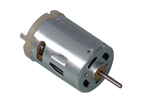
DC motors are really cheap and can be found very easily. In this post we will discuss the basic theory behind the DC motor drive system and its speed control. Having some basic understanding of how your motor driver works will play a key role in building your own circuits and debugging them.
The main advantage is that, they are really easy to interface. Hook the wires on to the battery terminals and they will work just fine. The direction of rotation is based on the direction of current flow in the armature (polarity of the battery). The below image illustrates the direction on the motor with respect to the direction of the current flow.
Okay, if you flip the wires connected to the battery terminals, the direction of rotation will change! But that is not gonna help much if you want the car to be remote controlled. So there has to be a way to flip the wires without having to touch it… That’s when an H-Bridge network comes into action.
H-Bridge
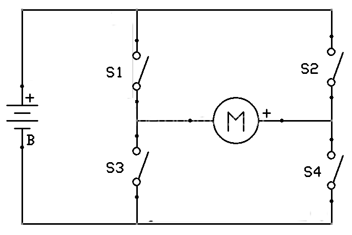
An H-bridge is nothing but a connection of the motor that resembles the letter ‘H’ in the English language.
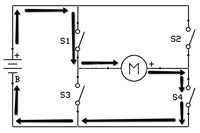
S1, S4 - ON and S2, S3 - OFF
Now if we were to turn on the switch S1 and S4 we will observe that the current flows from Battery positive to S1 and then to the motor and reached the negative terminal of the battery through S4.
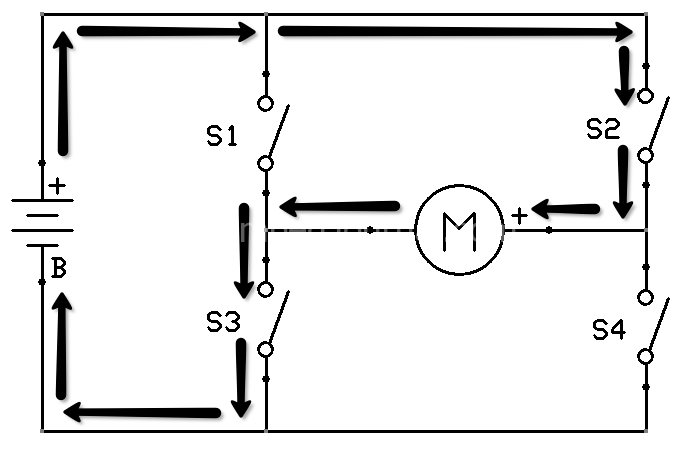
S2, S3 - ON and S1, S4 - OFF
Similarly, if we were to turn on the switch S2 and S3 we will observe that the current flows from Battery positive to S2 and then to the motor and reach the negative terminal of the battery through S3.
From the above cases you can see that the direction of current flow is reversed. Hence the direction of rotation of the motor is also reversed. This way we are able to drive the motor in both the directions without having to manually flip the wires.
Electronically speaking,
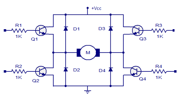
Yes, we do have to speak electronics! Switches S1 through S4 are replaced with transistors Q1 through Q4. Here is what it will look like once we are done replacing the mechanical stuff with electronics,
The 1k ohm resistors connected to the base of all the transistors are meant for current limiting. The diodes connected parallel to the transistors are called free-wheeling diodes and are used to prevent the transistors from getting damaged due the back currents (inductive) during switching.
In the above circuit, all the transistors are NPN so they turn on if logic 1 is given to them and are OFF when no logic or logic 0 is given. The drawbacks of this network is that there are 4 IO pins required to drive one motor. A slight variant of this connection is shown below,
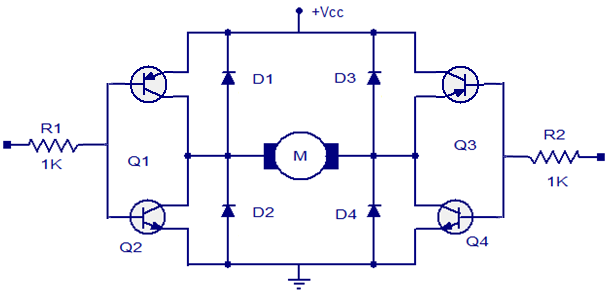
Here two transistor are paired and then used with a single IO pin. Here one of two transistors is PNP so, it needs logic 0 to turn ON. So if we were to give Logic 1 to one pair, then only the lower transistors (NPN) are turned. Similarly a logic 0 will turn on only the upper transistors (PNP). This way we are able to reduce the number of microcontroller pins required to the control the motor. This is the sort of circuit our L293d drivers use.
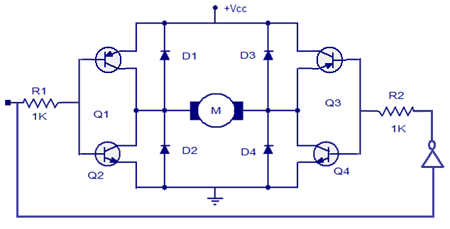
There is yet another configuration that uses only one pin to control the motor.
This is nothing but the previous connection with a NOT gate connected in between both the inputs. So if logic 0 is given then one pair will get logic 0 and the other will get logic 1. Hence the motor will rotate in one direction for logic 0 and another direction for logic 1.
The obvious disadvantage is that there is no way to stop the motors. All you can do is change the direction of rotation.
L293 Motor Driver
Fortunately, you don’t have to worry about all the circuits discussed above. There is a discrete IC (L293) that will handle all the electronics internally. The L293 is the most commonly used motor driver in robotics.
The IC is divided into two channels, one channel contains one motor and its control signals. So one side of the IC (pin 1 to 8) is channel 1 and the other side (pin 9 to 16) is channel 2. You can see that each side has an enable pin (pins 1 and 9) they are used to turn ON/OFF the control for that channel.
The pins labelled as Motor +ve and Motor -ve (pins 3,6,11, and 14) is where the motor has to be connected and the Logic A and Logic B (pins 2,7,10, and 15) are where the control signal to that particular motor has to be given.
Vcc1 (pin16) is the supply for the IC and should not exceed 5V. Vcc2 (pin 8) is the supply for the motors (high voltage high current supply). The two Vcc are internally isolated. The ground (-ve terminal) of both the supplies (Eg., 5v for IC and 12v for motors) should be connected to the ground pins (pins 4,5,12, and 13).
Choosing the right motor driver
As your robot size increases, you will find that you need bulkier motors which draw more current from the supply to carry the payload. L293 can supply up to 1 Amp per channel if your motors draws more current then there is the L298 which can supply upto 2 Amps per channel.
If your motor still needs more current (that’s got to be one hell of a motor) then you have to build your own motor driver like the one shown in the circuits above. You might need to replace the transistors in the circuits with suitable (current rating) MOSFETs.
Speed Control Techniques
The speed control of a DC motor is always done by controlling the input supply voltage. There are various methods used to vary the speed of the input voltage such as the potential divider method and the variable resistance method. But those methods are lossy as they linearly cut the current. An effective way to achieve voltage control (thereby speed control) is to use Pulse Width Modulation (PWM).
Pulse Width Modulation (PWM) Techniques
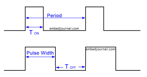
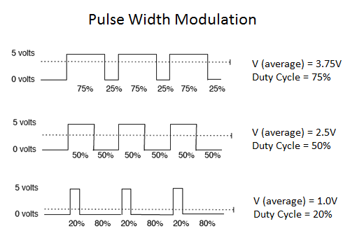
In this method, the width of the pulse is varied while the frequency of the pulse train is kept constant. In other words, the ON time of a pulse is varied while a total time period T is maintained constant.
As the figure illustrates, the width of the pulse has been changed from the first pulse train to the next pulse train. The ratio of the ON time to the total time T is called as the duty cycle. Duty cycle is always expressed in percentage or as fraction.
Now that you know what PWM is, lets discuss why we need it and how it can be used to vary the voltage and hence vary the speed of the motor.
Speed Control with PWM
When such PWM signals are given to the motors, they are turned ON for some time and turned OFF for some time. By varying the ON time, we are varying the time of exposure of the supply to the motors. Hence the average voltage supplied is varied.
So if we give 75% duty cycle, we are giving 75% of the supply to the load (motor). Similarly, when we give 20% duty, we will be giving only 20% of the total supply to load.
This signal is given to the enable pin of the L293 to control its speed. In case of a MOSFET based drive, this signal is given to the gate terminal of the MOSFET.
In a future post I will explain the generation of PWM with PIC microcontroller and the calculation for producing the desired duty cycle.
