Here we are with a TTT (Tips, Tricks and Techniques) post again after a long time! Firstly I have to apologize for the recent inactivity in the blog. I’ve been a little busy over the last few months. But guess what! I have some good news!
I think I’ll soon be payed for what I love to do! Yup, I no longer have the privilege to legally call myself a student. But personally I think I will be a student for ever! learning new things from new people… sounds like a lot of fun eh?
Back to the topic at hand, Hardware debugging is ‘not easy’;
PS. I didn’t use ‘difficult’.
The reason I say this is that, there are no guarantees that a particular strategy will work for a given problem. There are a lot of dependencies and things can crazily go wrong. But hey, you are not totally lost.
Most of the problems can be solved by following some SOPs (Standard Operational Procedures not Statement of Purpose :-P) to solve almost all the problems that you might face during hardware design.
There are some ground rules that you should follow closely before you even have a shot at circuit debugging. Now, if the IC’s are burnt, there is no use sitting with the hardware for hours together is there?
So here are the do’s and don’ts before starting a circuit debugging session!
Soldering practice
A good soldering practice will take a lot of burden off your shoulders. Use a lot of soldering flux to wet the solder plane so the contacts are made properly. In some cases, the oxidation on the leads of the component paired with insufficient solder flux will make a solder joint around the component’s leg so that it does not touch it at all.
Stick to the conventions
If something has been around for some time, then there is a reason why it has been there. So stick to colour convention while wiring up things (Red for power, Black/Brown for ground and Yellow/Blue for signals). This might take some effort but it’s totally worth the time you spent. It will also make it easy for other people to help you.
So use a lot of flux while soldering and hold the iron in the pad for a little longer and see if the solder has made a completely covered the lead without any gap! Trust me, this really helps. And last but not the least, do not pour too much solder in one joint and make it look like a big ball. Use little more that what is really needed. Again this comes with practice only so don’t give up hope!
No guess work!
At times when you are designing your own circuit you may come across a situation to decide on the resistance or capacitance of a network. Now you may be inclined to choose some value higher than the required to be safe but it is never advisable to guess the component values. This is not a kill situation but small approximations here and there can accumulate to cause an issue.

So take a pen and paper like in good old times and calculate the values! Read the datasheet of that component before making the circuit. Do you how to read a datasheet effectively? for more insight into this concept.
Don’t make messy breadboard connections
Most times it is advised to test the circuit in a breadboard before resorting to permanent solutions. Since it is temporary it does not mean it has to be messy and above all rules. Stick to the rules and you will be way better off. Here is an example, on the left is a circuit that I convinced my friend to build and the one on the right is the same circuit I built following all the above rules.
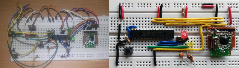
Now both the circuits are one and the same and they worked!! but I think the difference need not be mentioned. One can understand which wire is for what by just looking at the circuit. Here, I have used Red for Vdd, Black for Vss, Blue for all the system circuitry Yellow for SPI and Green for other peripherals (this case the LED).
Start over!!
Well don’t start over literally! Just go through the circuit diagram once again and test all the connections and the pin numbers. You will be surprised to see that you have indeed made a lot of careless mistakes. This technique helps you solve very small mistakes which otherwise would have taken hours of your time.
If you have a colleague or a friend nearby you could ask them to have a look at it too. This helps even better as your friend is going to be objective.
Clean Up!
After you are done soldering, you will notice that there are a lot molten soldering paste sticking around the soldering joints. Well this could be pain in two ways, one your circuit will stink and it will be sticky. The second and more pressing issue is that it obstructs your view of the solder ground.

How does that even matter…? well you won’t know if there was a short circuit in between adjacent soldering joints. If you do not have atleast 2 to 3 years of soldering practice, you most likely would have goofed up somewhere (no offence).
So Clean up! use a cleaning solution like the IPA or any other solution sold at your favorite electronics store.
Circuit Debugging Techniques
Once you make it a practice to do all the above, the number of pit falls that you tend to fall into is reduced considerably. Now we will discuss some aspects that will help you if you had some troubles in spite of all the above cautions.
Mind you, there is no generic solution to hardware problems. Every situation is unique and hence the best we can do is systematically approach the problem and try to find out the corner stone. I will list out some of the methods that I have found to be useful in debugging faulty hardware.
Resist the Urge!
Once you are done making the hardware, resist the urge to plug it in and see if everything is working as expected. First plug out all the sensitive (active) components such as the microcontroller and other IC’s before you power it up.

Now take a multimeter and check if all the power terminals are getting the correct voltage and polarity. Also put the multimeter in connectivity mode and check if there are any unwanted connections (short circuits) between adjacent soldering joints.
Divide and Conquer
Fault detection accounts for half of the fault correction process. As usual like in any problem, split it into multiple manageable parts and meet them one at a time. The key to a successful debug lies in identifying the fault region as soon as possible, so isolate blocks of circuits and test them separately. This will help you pinpoint the location of the fault.
Power Electronics Stuffs
If you are dealing with a lot of MOSFETs , IGBTs and Transistors, you should be equipped with how these devices act under fault conditions. For example, if a transistor were to fail, there would be a short circuit or very low voltage between the Emitter and the Base or Collector and Base. In case of MOSFETs and IGBTs, there would be a short circuit between the drain and the source.
There are no rules that the faults should occur at this specific pattern. The above observations are based on the personal experiences that my friend and I have had while building and testing some circuits. There is not better teacher than experience so go ahead and experiment for yourselves.
Use the Scope!
Sometime you’ll have to see what is actually going on down there as its is not always possible to analyze circuits from your mind. Most times, a DSO or an old school CRO could save you a lot of time by telling us exactly what is happening in your circuit. Check the output waveform with a scope and see if you are getting the required voltage and current magnitude.
Have something Useful?
Ya, you guessed it right! thats all I could think of now (I have a really bad memory). If you can think of any other method that worked out for you and feel that it might help someone else too, feel free to share your ideas/thoughts/suggestions in the comments section and I will update the post with your input. As always I will keep updating this post if anything pops up later on.


