Hack a toy car to make a cheap wireless robot? Yes, cheap toy remote cars form china can be scavenged to get their remotes to work with our robots. All of us have seen and played with toy cars some time in the past. Some -like me- might have bought them to get the magnets inside those DC motors. I don’t know why those C shaped magnets caught my attention more than the car.
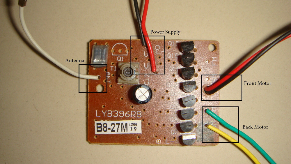
I have to admit even after growing older, I could not resist the urge to open a toy remote car that my little brother had just broken (he broke the axle connecting the rear wheel and it was beyond repair). It was one of those cheap china products so no big deal. What I was interested in was the remote control. Here is an image of the remote and its receiver board which apparently was the H-bridge too!
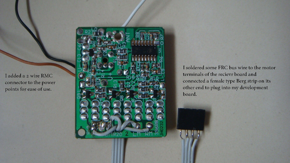
Even the cheapest RF ASK modules cost around $7 and this entire car was priced at around $10. Let’s say we just want the remote. Even then we can never make such a good looking enclosure for the transmitter in case of the RF module. This is the receiver cum motor driver circuit. I had seen all the wires and where they went so I didn’t have any trouble identifying them. But you could see the silkscreen and identify the wires.
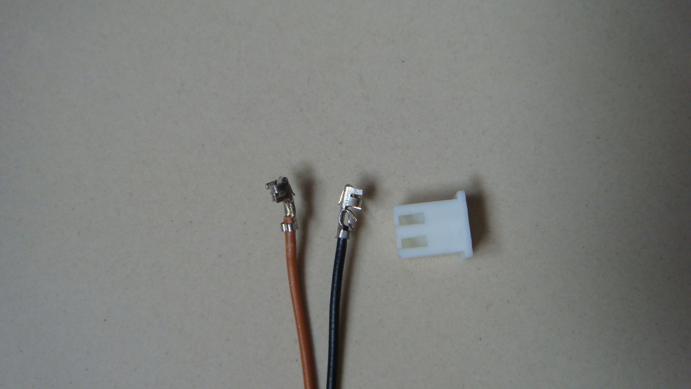
The next thing I did was, desolder those wires and add some custom wiring that could be plugged into my development board without looking messy. I soldered a 2 wire RMC connector to the power connectors so that I won’t mix up the positive and negative leads. Then I added a bus wire to take out the motor terminals and connected a female berg strip to its other end.
The RMC connector that I had soldered on the power terminals was actually a bad idea. My development board did not have a suitable connector to receive the connector. I could have desoldered it and attached a berg jumper, but my iron takes its own sweet time to heat up. Besides I needed those connectors when I moved the board into the robot where it is going to stay for sometime before I get tired of it. So this was the most optimal solution that I could think of, the white casing around the RMC connector had to go, good old tricks sometimes saves a lot of trouble.
The idea is that, the four pins that came out of the board was to serve as inputs for the Microcontroller or directly be given to a motor driver IC like L293 or L298 depending on the size of the the motor your robot has.
For doing either of the above, we need to have a table of how the board would behave for various types of input. To figure this out I had to connect LEDs to the output of the receiver. My PIC development board, conveniently had 4 LEDs with a 4 pin male berg strip (trust me its pure coincidence :-)) all I had to do was to plug it in to see the output. You can also see the power cables connected to the power terminals of the board.
The next part was really simple, just send some signal form the remote to note down the LED patterns. When the LED turns on the corresponding bit has a logic HIGH. As soon as I saw the first pattern the remaining were quiet obvious. Here is what I observed.
| Direction | Binary Pattern |
|---|---|
| Front | 0001 |
| Back | 0010 |
| Left | 0100 |
| Right | 1000 |
I wanted to implement this setup in Balckboy. All I had to do was remove some module (line sensors and comparators where not needed) from the robot and add this receiver and connect the inputs to PORT B.
Since the Blackboy already has a motor driver and a PIC microcontroller in it, I had to write a small program to get these values as inputs and move the robot accordingly instead of the much simpler alternative.
/*
 * File Name: remote_car
 * Author: Siddharth Chandrasekaran
 * Created on July 7, 2013, 9:03 PM
 * Hack a Toy Car to Make a Cheap Wireless Robot
 * Visit http://embedjournal.com for more codes.
*/
#include"p18f4520.h"
#define FRONT 0x06
#define BACK 0x09
#define LEFT 0x05
#define RIGHT 0x0A
#define STOP 0x00

#pragma config WDT=OFF,OSC=HS, LVP=OFF, IESO=OFF, FCMEN=ON, XINST=OFF

void main()
{
    ADCON1 = 0x0f;
    TRISC = 0x00;
    TRISB = 0x0F;
    while(1){
        if(PORTBbits.RB0 == 1)
            LATC = FRONT;
        else
        if(PORTBbits.RB1 == 1)
            LATC = BACK;
        else
        if(PORTBbits.RB2 == 1)
            LATC = LEFT;
        else
        if(PORTBbits.RB3 == 1)
            LATC = RIGHT;
        else
            LATC = STOP;
    }
}
Thats all folks! Here is a video to demonstrate the output of the above procedure.
Hope you like it. If you have any queries/suggestions leave a comment and I will try to answer then to the best of my abilities.


