In my previous post Introduction to Stepper Motors and How they Work, we had a look at stepper motors and how they work. This post will deal with the programming and circuitry involved in the stepper motor interface with PIC microcontroller.
Usually a microcontroller is used to produce the stepping sequence for the stepper motor. But this is not the only method of producing the stepping sequence. It can be produced by using flip flops, logic gates and some knowledge about digital electronics. But this post will deal with the former method as it is better and easier.
Need for a driver circuit:
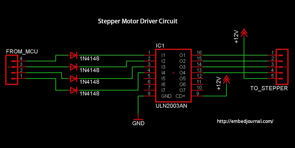
Your microcontroller works at 5V and the stepper motor will need 12V to operate. So the microcontroller port pins can’t drive the motor on their own. They need something called as the driver circuit. This circuit typically takes low level signal from controller and converts them to high voltage/current signals that are capable of exciting the stator windings.
Depending on the current and voltage requirement of the stepper motor, the driver circuit has to be built. For this post, I will be using the smallest stepper motor that I have with me. This is just to avoid building dedicated power diver circuits.
If you don’t have a small one, you will need driver circuit. For now I will assume you do have a small motor with you. If you don’t, I will write a tutorial on making a driver circuit sometime in the foreseeable future.

Entire Setup
Here is the set up that I made for the interface. For a change I thought I will build this circuit over a breadboard instead of the conventional development board setup in my posts. It took more time and looks a lot more messy, but some things are worth the time spent over it. This is a fully standalone circuit which just needs a 12V supply.

The Circuit:
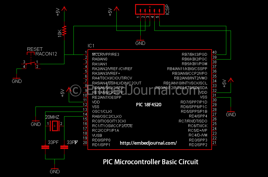
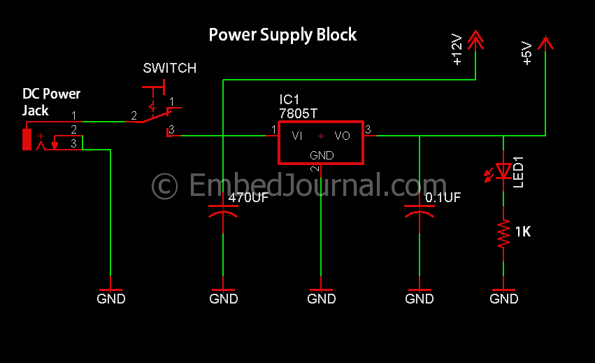
Here is the top view of the breadboard. I have separated the circuit into various sections. Below are the schematics of each of the blocks mentioned. Click them to enlarge. I think its quiet self explanatory and nothing more needs to be said.

Programming
The programming is really simple and can be done with just a few lines of C code. But before you go into it, you might want to take a look at my previous post on the stepper motor basics to understand the program fully.
In the following program I have included all the three types of stepping sequences in three arrays that are selectable with Macros. Hence to use the code for full step mode, you will have to make define a macro, FULL_STEP
For those who don’t already know, #ifdef MACRO_NAME checks if macro MACRO_NAME is defined. If so, the lines that are in between the #ifdef MACRO_NAME and #endif statements are added to the program. If such a macro is not defined, then the lines in between them are commented out.
So basically, it is an if statement but in terms of pre-processing. Needless to say, the same logic applies to the if-else statements.
/*
 * File Name: stepper.c
 * Author: Siddharth Chandrasekaran
 * Created on July 14, 2013, 7:47 PM
 * LCD Library For C18 compiler and PIC advanced 8 bit CPUs
 * Visit http://embedjournal.com for more codes.
*/
#include<p18f4520.h>
#include<delays.h>

#pragma config WDT=OFF,OSC=HS, LVP=OFF, IESO=OFF, FCMEN=ON, XINST=OFF

#define DELAY 10
#define HALF_STEP    // change this for the mode of excitation.

#ifdef HALF_STEP
#define SEQ 8
#else
#define SEQ 4
#endif
#ifdef WAVE_DRIVE
unsigned char stepping_seq[4]={0b00001000, 0b00000100, 0b00000010, 0b00000001};
#endif
#ifdef FULL_STEP
unsigned char stepping_seq[4]={0b00001100, 0b00000110, 0b00000011, 0b00001001};
#endif
#ifdef HALF_STEP
unsigned char stepping_seq[8]={0b00001000, 0b00001100, 0b00000100, 0b00000110,
                               0b00000010, 0b00000011, 0b00000001, 0b00001001};
#endif

void main()
{
    unsigned char count = 0;
    TRISD = 0x00;
    while(1)
    {
        if (count == SEQ)
           count = 0;
        LATD = stepping_seq[count];
        Delay10KTCYx(DELAY);
        count++;
    }
}
Video of the stepper motor in action!
In this video, I have used the wave type stepping sequence. I’m sure there is not much noticeable difference between the various types of stepping sequence so I didn’t bother to record all of them. You can also see the change in speed with the change in delay in between each step.
Hope this post was helpful in understanding stepper motor interface basics. If you are facing some issues or have some questions, post them in the comments section below.


