Stepper motor is a specially designed DC motor that can be driven by giving excitation pulses to the phase windings. They cannot be driven by just connecting the positive and negative leads of the power supply.
They are driven by a stepping sequence which is generated by a controller. The motor moves in steps according to this sequence. This post will discuss the basic theory behind the stepper motors.
Printers are a great source for stepper motors. Old dot matrix printers have a big and a small stepper motor. These are the stepper motors that I was able scavenge out of old dot matrix printers from my dad’s office.

Applications
Stepper motors find their application in industrial automation and robotics due to their ability to move in steps. These motors are used in IC fabrication units. These motors play an integral part in the design of CNC (Computer Numeric Control) machines and x-y plotters.
Basic Classification of Stepper Motors
Based on the type of the construction, stepper motors can be classified as
- Variable Reluctance (VR) stepper motor
- Permanent Magnet (PM) stepper motor
- Hybrid stepper motor
Variable Reluctance (VR) stepper motor
The Variable Reluctance stepper motors are those which have a rotor made of ferromagnetic substances. Hence when the stator is excited it becomes an electromagnet and the rotor feels a pull in that direction. The ferromagnetic substance always tries to align itself in the minimum reluctance path.
By exciting the coils, a magnetic field is produced and air gap reluctance is varied. Hence it is called a variable reluctance stepper motor. In this motor, the direction of the motor is independent of the direction of the current flow in the windings.
Permanent Magnet (PM) stepper motor
Here the rotor is permanently magnetized. Hence, the movement of the motor is due to the attraction and repulsion between the stator and rotor magnetic poles.
In this motor, the direction of the motor is directly dependent on the direction of the current flow in the windings as the magnetic poles are reversed my changing the direction of the current flowing through the rotor.
Hybrid stepper motor
The hybrid stepper motor, as the name suggest is a motor designed to provide better efficiency by combining the pros of both the permanent magnet stepper motor and variable reluctance stepper motor.
The VR and PM stepper motors are the most common type of stepper motors. The only difference is that, in the variable reluctance stepper motor, the rotor is made of a ferromagnetic substance and in the case of permanent magnet stepper motor, the rotor is permanently magnetized.
A look inside stepper motors!
Since I did not buy the motors (technically I did buy them; but not literally) I did not have a clue as to what the construction of the motor was.A Besides, there were no warranty issues that I had to worry about.
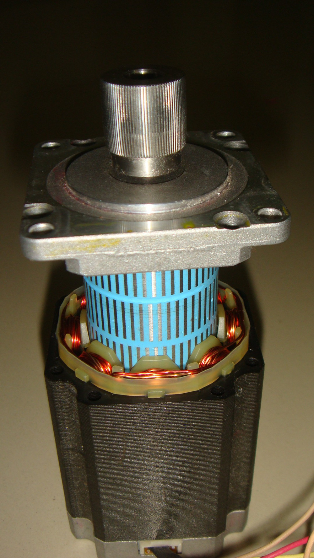
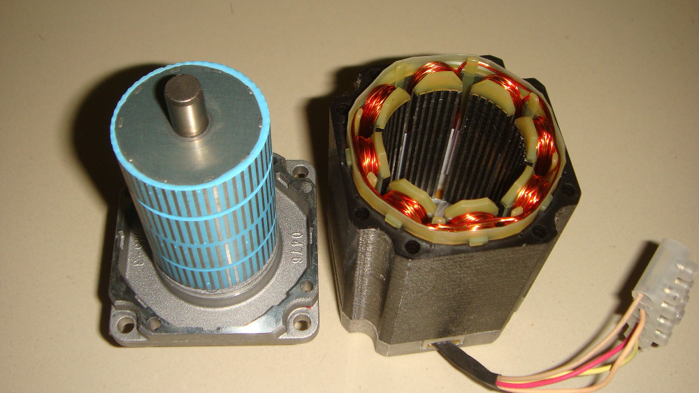

Once I opened the enclosure I found out that I had a hybrid stepper motor. This motors also had multiple poles in the stator and rotor.
Stator
The stator had four wires coming out of the motor and each of the poles (wound with copper wire) had teeth projecting out of them. Hence each of their projected teeth behaves as separate poles for the stator. Here is the image of the stator showing the projected poles.

Rotor
The rotor arrangement took me some time to understand. The horizontal lines marked in red and blue are the poles of the rotor. It so happens that the red lines are magnetic north poles and the blue lines are magnetic south poles.
Similarly the first column is South and the last one is North. Each column is called a stack and this motor is a multi stack motor (or a four stack motor going by the numbers).
It might be hard to observe in the image, but look closely at the place where the water mark appears, you can see that the poles of adjacent columns are arranged in a zig-zag manner. The only logical explanation as to why they did that could be - to decrease the stepping angel further.

For calculating the step angel and number of steps per rotation, I should to count the stator and rotor poles. You can’t possibly imagine what a tiresome job it is unless you have had to do it. For now, I will give the motor some rest and move on to the smallest motor so that I don’t have to worry about the power electronics involved in driving this massive motor.
Identifying the wires
There are stepper motors with a range of wires coming out of them. I have seen 4, 5, 6 and 8 wire stepper motors. This is method to sort out the wires. If you bought the motors from a vendor and know the winding configuration from the datasheet, skip this testing part if you are in a hurry.
But this can be helpful some day (the whole world is throwing out old printers and you’ll never know when you’ll get lucky).
The trick in identifying the wires of the motors is that, the motor’s stator winding will have a small resistance. There can be motors that fall into one of the four categories (judged by the number of wires they have), as shown in the image below.
Once you have determined the winding diagram for your motor, you can take a multimeter and start measuring the resistance between wires.
- First choose one wire (any wire) and have it as a test point.
- Start noting down the resistance between that wire and the other wires. Keep the range of the meter to some minimum value (say 0-200 ohm).
- Some should return “1.” (1 means that the value of resistance goes out of the range chosen) This means that the current wire and the wire you just tested are not connected and hence have infinite resistance.
- The other cases you can determine logically. If you assume A - A’ resistance is 2R then A - COM should have a resistance R.
Note: The above method will fail for the 5 wire configuration. If you worked that out already- great! else, all the wires will have contact with each other and all will read a resistance of 2R except for the COM which will read just R. The trick is to find COM and then use conventional techniques of circuit analysis for identifying the winding.

Stepping Sequence of Stepper Motors
As I mentioned earlier, stepper motors are not driven by normal excitation but a sequential excitation of the adjacent phases. Such a sequence is called, a stepping sequence as they are in steps.
Wave Drive Sequence
This is one type of stepping sequence. In this method, one phase is one at a time. That is, when phase A is excited, all other phases are OFF. Similarly before exciting the next phase, the first is turned OFF. The windings are excited one by one for a finite duration like a wave, hence the name. Here is the stepping sequence diagram.

Full Step Sequence
The full step sequence or the 2 phase ON sequence, is when two adjacent phase windings are excited at a time so that the rotor is positioned at a point resultant to both the fields. Here is the stepping sequence diagram.

Half Step Sequence
This sequence is the mix of both the wave drive and full step stepping sequence. The first one of the each of the above methods is used to from the first two of this message. By using this sequence, as you can see, the stepping angle is reduced by half.

Micro Stepping
This is the last of the methods of stepping sequence. Here the excitation current is varied gradually. When the rated current is applied to the phase A and phase B is not excited, the rotor is at vertical position (step 1 of the above diagram).
Now gradually the current to phase A is reduced and the current to phase B is gradually increased. Hence the rotor will move by a small angle due to the resultant magnetic field intensity of phase A and phase B.
When the current in phase A is further decreased and the current to the phase B is increased the the rotor keeps moving clockwise in very small stepping angels. When the magnitude of currents in both the phase A and phase B is equal then the magnetic field intensity is equal and hence the rotor will be positioned in between the two phases (Step 2 of the above diagram).
After this, the the same procedure is repeated to bring the rotor from step 2 to step 3 of the above diagram. Using this kind of excitation we are able to achieve a smooth movement of the rotor. As you might have guessed, this method is more complex than the other methods discussed earlier.
What readers had to add:
Case #1
A reader Lalomania came up with an interesting question in reddit and I felt it should be added here. You can read the actual thread here.
“The only logical explanation as to why they did that is to further decrease the stepping angel. Isn’t this zig-zag arrangement essential for the motor to work. Wouldn’t the poles of the rotors cancel each other otherwise?”
What I meant was that, in each of the horizontal pole stack, say they just placed alternating poles, there should be some gap in between adjacent poles so that the pole strength wouldn’t weaken over time. Stepping angel is measured from center of one pole to another which in this case would include the gap also.
By having separate stacks for each pole and having them in zig-zag manner, when viewed vertically (from top) the poles will seem to be alternating though discrete through the height of the cylinder. The gap is not really needed except in between two stacks. Hence the stepping angel will exclude the gap. Ergo, reduction in the stepping angle.
Case #2
Here is another response, again from reddit that had to go here. Jtl3 provides some notable differences between the motors that some might find interesting.
When trying to identify permanent magnet vs. variable reluctance motors, PM magnets are often made of folded steel and are quite small with low rotor inertia. They are typically of poor construction. VR motors are typically long and slender, and tend to have much looser bearings. They can be spun very rapidly and often make a ‘whooshing’ noise.
Neither ‘cog’, a distinctive feature of hybrid motors (when you turn them, they feel stiff and grainy; the magnets aligning with the pole laminations allow you to feel the steps.)
There are interesting ramifications to the differences in construction, too. PM motors are much cheaper because they can be cast instead of having to be made from laminations. VR have comparatively poor torque because of similar issues as found in induction motors.
VR motors are almost exclusively driven in whole-step mode, but can achieve much smaller step distances, as they do not have the issues from stator geometry like PM do. Hybrids’ have higher torque and are quieter, yet retain the step distance abilities by replacing the rotor with a magnetized one. PM & hybrid are the only types ever micro stepped, as true VR cannot be (due to how the rotor is magnetized through inductance).
Conclusion
In the posts to come, we will discuss the interface of stepper motors with microcontroller to observe how they behave for various types of excitation and probably discuss some power electronics involved in delivering the high current needed by the big motors (like the one that was opened in this post).


