The I2C protocol also known as the two wire interface is a simple serial communication protocol that uses just two pins of a microcontroller namely SCL (serial clock) and SDA (serial data). This is a very popular protocol that can be used to address a large number of slave devices that are connected to the same bus. This protocol comes in handy when there is scarcity of available pins in the microcontroller. Each slave device has a slave address or a name for which they respond. This is usually a 7-bit binary number. Once a master sends a valid slave address, that slave alone will respond to the master’s queries and all other slaves will ignore any conversation between the master and that particular slave.
There are a number of conditions that can be made over the I2C bus such as start and stop sequence. The data line does not change when the clock line is HIGH. If the data line changes when the clock line is High, the slave device interprets it as a command and not as data. This is the only feature in the interface that puts a distinct line between the command and data.
I2C Protocol Timing Diagram:

Understanding the Start and Stop sequence of I2C Protocol:
The timing diagram above has the start sequence shown in the dotted box to the left. Here if you notice the data line SDA is having a High to Low transition when the clock line SCL is HIGH. Under normal circumstances this does not happen as you can see in the subsequent clock pulses that the data line is stable in one state, either HIGH or LOW when the clock line is HIGH. Similarly to the right most side of the diagram you will find another dotted box with the stop sequence (see the one with the solid line inside the box). The data line experiences a LOW to HIGH transition when the clock line is HIGH.
Besides this there is also a “Repeated Start” condition which allows a master to continue the current transaction without losing atomicity. This is achieved by NOT sending a stop after the transaction but sending a Start in its place.
Application:
The I2C protocol is quiet easy to understand. The working of the protocol is illustrated in the following content,
The rule of thumb is that every time the slave devices experiences Start sequence it expects a 7-bit slave address along with a read/write specifier in the MSB (0 - for write and 1 - read). If the specifier is set to write then the next data written will be the address to the register to which the consecutive data is to be written. The device automatically increments the register pointer after a success full write. On the other hand if the specifier is set to read then the incoming data from the bus will return the value of the register to which the stack pointer was last pointing to and the consecutive registers following it.
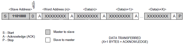
Sequentially write data to a slave device with I2C Protocol:
Here, the slave address with the write specifier is sent after the Start sequence. The slave sends an Acknowledge to the master (MCU). Then the next byte of data written to the slave device is the address of the register to write to. Following this there can be any number of sequential write operations with slave sending Acknowledge after every byte of data written to the register starting from the register specified by the address and sequentially moving up after each write operation. This can be terminated by sending a Stop sequence.
Sequentially read data from a slave device with I2C Protocol:
Initially the slave address with the read specifier is sent after the Start sequence. The Slave sends an Acknowledge to the MCU. Following this there can be any number of sequential read operations with master(MCU) sending Acknowledge after every byte of data read from the register last written in the write operation (since, address of the register to read from is not specified here). This sequential read can be stopped by sending a Not Acknowledge signal followed by a Stop sequence

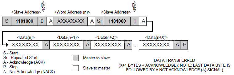
Sequentially read and write data as a combination of the above two methods:
This process is just a mixture of both the sequential read and sequential write methods. Initially the slave address with the write specifier is sent after the Start sequence. Then the next data to be written will be the address of the register in the slave device over which the operation is going to be performed. Once this is done a repeated start sequence is made and and the 7-bit slave address with the read specifier is transmitted. Following this there can be any number of sequential reads from the register address specified in the previous step along with all the registers that follow it. The register address is automatically incremented by the device. The sequential read will involve the master (MCU) sending an Acknowledge to the slave after every byte of data read. The repeated read process can be stopped by sending a Not Acknowledge signal followed by a stop sequence.
This is the bare minimum that any programmer should know to get started with using devices that interfaces using the I2C protocol. There is lot more to this protocol than this. So I suggest you download the Philips user’s manual for the same if you are going to do anything serious.


