I wanted to make a breadboard breakout for PIC microcontrollers after seeing this arduino breadboard breakout from adafruit. This product is fully standalone and yet has very small footprint so that it can be conveniently plugged into the breadboard. The most amazing part was that it still has 2 rows on each side of the breadboard for the user to jump wires.
First I thought of making a breakout board for the 40 Pin DIP package that I usually use. Then I realized that is was almost impossible to fit the controller & its circuitry and still have space on the breadboard for other use. So I decided to use the 28 PIN package (similar to the arduino) to have a fair game.
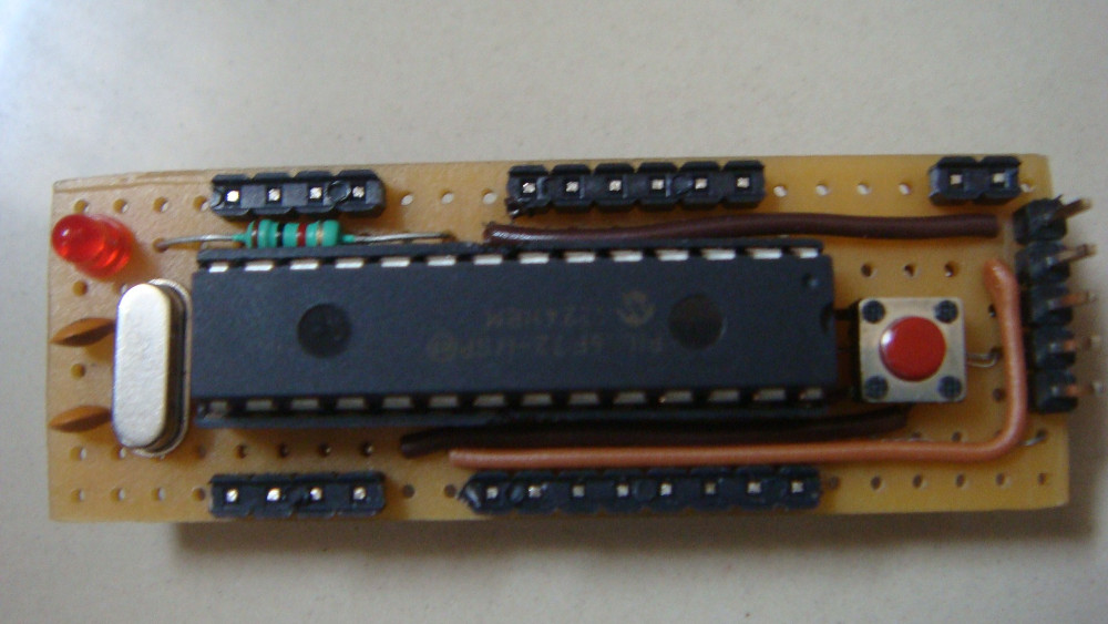
This is the image of the fully standalone breadboard breakout for Microcontrollers that I made earlier today. By saying fully standalone I mean to say that the board doesn’t need any other external component for the controller to work (except ofcourse the power supply). This board, like the adafruit’s board also leaves 2 rows on the breadboard for the user.
One major challenge I faced while making this board is the lack of board room. I wanted to give it the same feel as the adafruit’s breakout board. Hence, the dimensions of the board were already decided. I also did not want the board to look really messy with wires jumping here and there on the top. At the bottom, I obviously cannot have wires jumping around as it has to be plugged on to the breadboard.
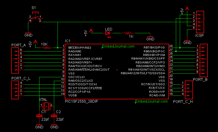
Circuit Diagram
The one thing that has to be appreciated with PIC microcontrollers is that they maintain uniform PIN arrangements. This is not just true in between controllers of the same series but controller with same pin count.
For example, I built this board for PIC 18F2550 and this is perfectly compatible with PIC 16F72
This is the circuit that I had to get into the perf board. The male headers had to be soldered to the bottom side while the others remain on the upper side. After a lot modifications and alterations, I was able to get the circuit into the perf board.
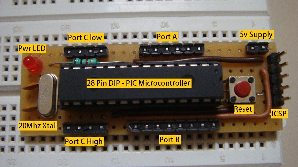
Cheat Sheet
The board can be powered by the Pickit 2 or can be externally powered with the power connector. It has an on-board reset switch, crystal, ICSP connector and power indicator.
Port A is as usually analog and has only 6 pins. Port B and C are 8 bit wide and are separately addressable. Port C is broken into two nibbles (high and low). You can also see that there is a lot of room for prototyping on the breadboard after the breakout board has been inserted.
Another Look
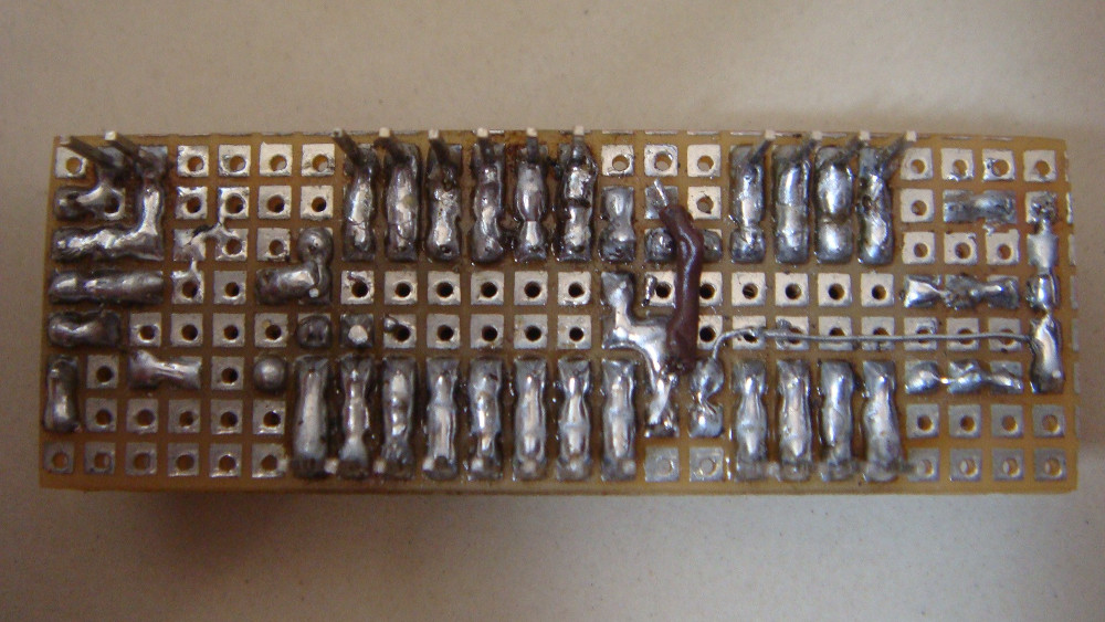
Here is the back side of the board. Inspite of my best efforts, I could not do without a wire at the bottom of the board. It’s a little messy, but solves the purpose very well.
This board occupies very little space on the breadboard, which allows us to use the remaining space for other peripherals. It is also really useful for rapid prototyping and proof of concepts. I look forward to do a lot of projects with this breakout board in future.


