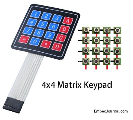
In this post we will discuss logic and interface of a matrix keypad (4x4 for this post) with microcontroller to reduce the number of port pins required to read a certain number of inputs (digital). The same logic applies to any matrix keypad of order NxN. Where, N is the order of the matrix.
Why Matrix Keypad?
Typically one port pin is required to read a digital input into the controller. When there are a lot of digital inputs that have to be read, it is not feasible to allocate one pin for each of them. This is when a matrix keypad arrangement is used to reduce the pin count.
Therefore, the number of pins that are required to interface a given number of inputs decreases with increase in the order of the matrix.
Example: If the matrix is 2x2, you will need 2 pins for the rows and 2 pins for the columns. In such a case there is no difference in the cost of reading that many inputs. But if you consider a 10x10 matrix you will just need 20 pins (10 for the rows and 10 for the columns) to read 100 digital inputs.
How is it wired up internally?
Here is how the matrix keypad is wired internally.
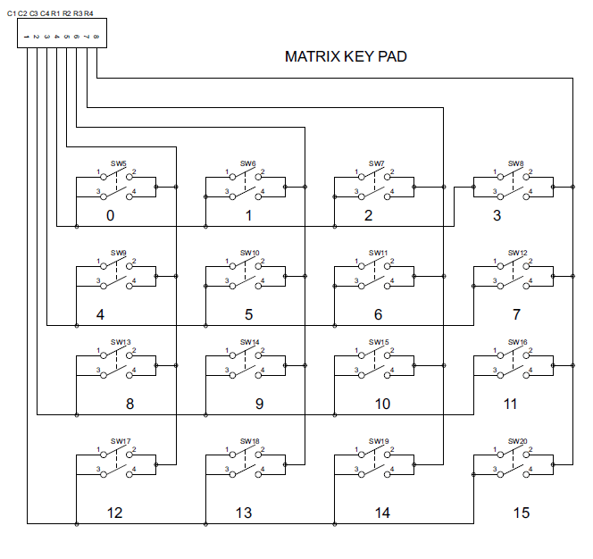
From the circuit you can see that when one of the 16 buttons are pressed, a pair of pins are connected together. We will use this feature to detect the button that was pressed in the following sections.
Matrix Keypad Interface Logic
Initially all switches are assumed to be released. So there is no connection between the rows and columns. When any one of the switches are pressed, the corresponding row and column are connected (short circuited). This will drive that column pin (initially high) low. Using this logic, the button press can be detected. The colors red and black is for logic high and low respectively. Here are the steps involved in determining the key that was pressed.
Step 1:
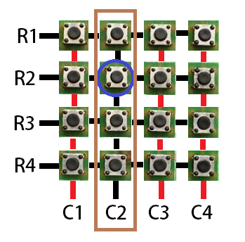
The first step involved in interfacing the matrix keypad is to write all logic 0’s to the rows and all logic 1’s to the columns. In the image, black line symbolizes logic 0 and red line symbolizes logic 1.
For now let us assume that, the circled key is pressed and see how the key press can be detected by a software routine.

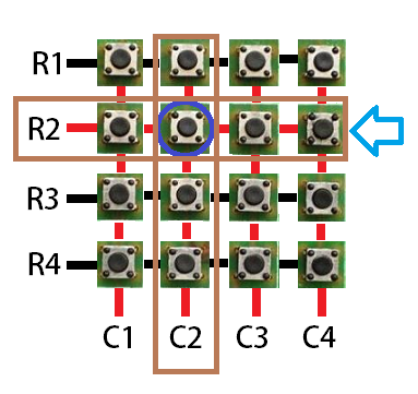
Step 2:
Now the software has to scan the pins connected to columns of the keypad. If it detects a logic 0 in any one of the columns, then a key press was made in that column. This is because the event of the switch press shorts the C2 line with R2. Hence C2 is driven low.
Note: color of the lines indicate the logic values they return.
Step 3:
Once the column corresponding to the key pressed is located, the next thing that the software has to do is to start writing logic 1’s to the rows sequentially (one after the other) and check if C2 becomes high. The logic is that if a button in that row was pressed, then the value written to that row will be reflected in the corresponding column (C2) as they are short circuited. Note: color of the lines indicate the logic values they return.
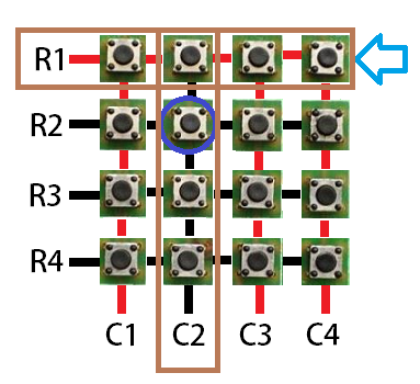
Step 4:
The procedure is followed till C2 goes high when logic high is written to a row. In this case, a logic high to the second row will be reflected in the second column.
Note: color of the lines indicate the logic values they return.
We already know that the key press happened at column 2. Now we have detected that the key is in row 2. So, the position of the key in the matrix is (2,2)
Once this is detected, its up to us to name it or provide it with a task on the event of the key press.
Implementation in C
Now lets see how the above logic can be implemented in embedded C. Here is the program I wrote to test it. This code is for PIC microcontrollers with c18 lite version compiler. I as usual, used a lot of macros so if you are an Arduino user you could easily make some alterations to the code and use it. The basic concept for keypad scan is inside the while(1) loop.
#include<p18f4520.h>
#include<delays.h>
#pragma config OSC=HS,WDT=OFF,FCMEN=ON,XINST=OFF,IESO=OFF,LVP=OFF

#define HIGH 1
#define LOW 0
#define R1 PORTBbits.RB0
#define R2 PORTBbits.RB1
#define R3 PORTBbits.RB2
#define R4 PORTBbits.RB3
#define C1 PORTBbits.RB4
#define C2 PORTBbits.RB5
#define C3 PORTBbits.RB6
#define C4 PORTBbits.RB7
#define SEG_EN1 LATCbits.LATC1
#define SEG_EN2 LATCbits.LATC0

/*-----Function Declaration--------*/
void seg_wrt(void);
void update(unsigned char);

unsigned char val = 0;

void main(void)
{
    ADCON1 = 0x0F;
    TRISD = 0x00;
    TRISC = 0x00;
    TRISB = 0xf0;
    LATC = 0x00;
    LATD = 0x00;
    INTCON2bits.RBPU = LOW;	// Enable Weak internal pull-ups in pin RB4 and RB5
    while(1)
    {
        LATB = 0xf0;
        if(C1 == LOW){
            R1 = HIGH;
            if(C1 == HIGH)
                update(16);
            else {
                R2 = HIGH;
                if(C1 == HIGH)
                    update(15);
                else {
                    R3 = HIGH;
                    if(C1 == HIGH)
                        update(14);
                    else update(13);
		}
            }
	}
	if(C2 == LOW){
            R1 = HIGH;
            if(C2 == HIGH)
            	update(12);
            else {
            	R2 = HIGH;
            	if(C2 == HIGH)
                    update(11);
                else{
                    R3 = HIGH;
                    if(C2 == HIGH)
                        update(10);
                    else update(9);
            	}
            }
	}
	if(C3 == LOW){
            R1 = HIGH;
            if(C3 == HIGH)
            	update(8);
            else {
            	R2 = HIGH;
            	if(C3 == HIGH)
                    update(7);
              	else{
                    R3 = HIGH;
                    if(C3 == HIGH)
                        update(6);
                    else update(5);
            	}
            }
	}
	if(C4 == LOW){
            R1 = HIGH;
            if(C4 == HIGH)
            	update(4);
            else {
            	R2 = HIGH;
            	if(C4 == HIGH)
                    update(3);
                    else{
                    	R3 = HIGH;
                    	if(C4 == HIGH)
                            update(2);
                        else update(1);
            	}
            }
	}
        seg_wrt();
    }   // end of while(1)
}

void update(unsigned char data)
{
    val = data;
}

void seg_wrt() {
    unsigned char lookup[]={0x3f,0x06,0x5b,0x4f,0x66,0x6d,0x7d,0x07,0x7f,0x6f};
    long unit,ten;
    long idx = 0;
    unit = val/10;
    ten = val%10;
    for(idx=0;idx<100; idx++)
    {
    	LATD = lookup[unit];
    	SEG_EN1 = HIGH;
    	Delay10TCYx(10);
    	SEG_EN1 = LOW;
    	LATD = lookup[ten];
    	SEG_EN2 = HIGH;
    	Delay10TCYx(10);
    	SEG_EN2 = LOW;
    }
}
Here is a video demonstration for the interface of the 4x4 matrix keypad using the above code.
The above program is done with polling and utilizes the entire time of the controller to scan the keypad and display the data on the 7 segment displays. There is a cool feature on Microcontrollers called as the Interrupt on Change (IOC). As the name suggests, the controller will interrupt if it finds any change in a port. In PIC the whole of PORT B has this feature. By using the feature without any change in the hardware setup we can scan the keypad in the ISR and have more of the controller’s time to do something useful.
In my upcoming posts I will use the IOC feature to interface the keypad.


