Input voltage measurement of an embedded device is not as simple as it sounds. But if estimated, can come in very handy in a number of occasions. In this article we will see how we can add this feature to your embedded system with minimal components.
It is one thing to measure the voltage and totally another to measure the input voltage. If you haven’t guessed the difficulty in it already, the ADC pins of the microcontroller measures form the Vref+ to the Vref-. In most cases Vref+ defaults to VCC and Vref- to GND. Vref can be configured through software to some other fixed voltage reference points (in some architectures) or have an external fixed bandgap voltage reference, for your ADC module.
But if that weren’t the case, then if system voltage was to increase or decrease, then the Vref values which are derived from the supply voltage will also change. This makes it hard to detect if there is variation in the input voltage.
Now why would we need to measure the input voltage for a microcontroller?
Well the question may sound unreasonable as long as you are not on a battery operated system. On a battery operated system, the battery voltage may vary with the state of charge of the battery. The battery curve is pretty stable for costly Lithium-ion batteries but that is not the case with low cost rechargeable and non rechargeable batteries. The voltage can vary from a .5v to 1v depending on cell chemistry and quality of the battery. Here are some reasons why you would need to know the input voltage.
- Battery is going to die and you want to shift to a low power consumption mode until replacement.
- Battery is going to die and you need to save enough energy to report this as an alert.
- To detect a brown-out before it occurs so that you could complete the current task and prepare for a shutdown.
- Adjusting ADC values based on the input voltage to get better accuracy.
With that said, having the feature to look into the supply voltage, gives a lot of flexibility to the developer to build a robust code.
Now there is a super-easy way and an okay-easy way to accomplish this. The super-easy way is to look for something called as band gap reference voltage in your controllers datasheet. If there is something like that then you are in luck! you do not need to add a single extra component to get this feature. Read along to know how to use it to determine the input voltage.
Well if you don’t, don’t worry, there is still the okay-easy way. Surprisingly, the circuit required to accomplish this so primitive that you will find yourself adding this into any project you make just for the sake of having it!
What’s the secret?
Its no secret that the forward drop of a standard PN junction diode is 0.7V. At least that’s what the textbooks say. But in practice you will have anywhere between 0.55V to 0.7V depending again on the make and quality. But for the sake of this discussion we will assume that it is indeed 0.7V. The value of forward drop for a given diode is constant and does not vary. This 0.7V is called as the band gap of the diode and does not vary with the supply voltage given to it so long as it is above the band gap voltage (in this case 0.7V).
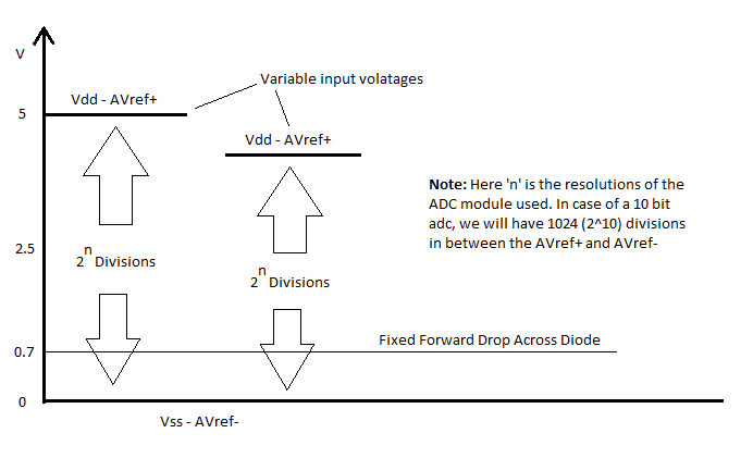
The image above shows that the input voltage in case 1 and case 2 has changes but the voltage drop across the diode remains constant. So if you have a 10 bit ADC, then you will measure 2^10 counts between the Vref+ and Vref-. Now if you know the number of counts the ADC would return for the diode drop at nominal system voltage, simple math will assure you that you can compute the current voltage from the measured ADC reading of the diode drop.
How to go about it?
If you are one of those lucky ones who have the internal bandgap reference, then you don’t have to do the next few steps. You could directly configure your ADC module to give the bandgap reference voltage and get on to the formula that is mentioned below (in the code).
For the others, a drop 0.7v is a little too low to measure with good accuracy especially if you are operating your device at 5V. So you should use two or three such diodes in series to produce a higher drop. Two diodes in series will give 1.4V drop. This is a little less than 50%(very good) in case of a 3.3V device. and somewhere around 25%(can live with it) in case of a 5V device.
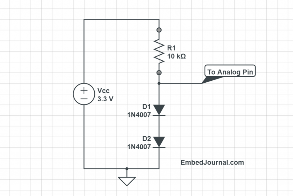
So, 2 PN junction diodes in series is your best bet at getting a reasonably accurate reading for both the voltage levels. But that’s not it. So far you have accounted for the 1.4V drop of the total supply but there is still the remaining voltage that has to be dropped. We also want the current through this network to be as low as possible. So you will have to add a 10K ohm in series as well. Here is how the entire circuit will look like.
To get the actual system voltage from the ADC, you should do something like this,
#define ADC_MAX_COUNT   1023   // 2^10 = 1024
#define BANDGAP_VOLTAGE 1400   // in mV

float getSystemVoltage()
{
  return ((float)ADC_MAX_COUNT/getRawAdcValue() * (float)BANDGAP_VOLTAGE);
}
I have defined two macros so that you do not have to change anything in the code. All you have to do is change the appropriate values in the first two lines (ofcourse you have to write your own implementation for getRawAdcValue). Note, the band gap voltage is expressed in millivolts.


