In this post I intend to provide a standalone, controller independent, Guide to Timer / Counter Module in Microcontrollers. The concepts explained are not associated with any one particular controller which might not be useful for all readers. To an extent this is an independent post but little exposure to Interrupts and how they work is a prerequisite, which may not be within the scope of this post. But otherwise this post should have everything you need to know about timer modules.
The Timer module is an integral part of any microcontroller family. Most of the modern controllers today have at least one timer module built into them. These timer modules, depending on the range of the microcontroller (baseline, mid-range, advanced) have various features such as, prescaler postscaler, auto-reload, ability to work as a counter and so on. Any application small or big has its need for a timer. So as embedded engineers, it is a must to have a working knowledge of how they work and behave.
A Timer / Counter module may derive its clock source from the system clock and perform counting operation based on this clock pulse. In this case it is said to work as a timer and perform time measurement operations. Since the system clock frequency is determined by the user and it is often quite stable, the programmer is able to achieve accurate time interval by suitably configuring the timer module.
A Timer / Counter module may behave as a counter, counting the external events on one of the controller’s pin. In this case the clock source for the timer may be assumed to be obtained from that external source, and It is said to behaves as a counter. The programmer may then use this data according to the requirement of the application.
In both the cases the timer / counter module can be configured to interrupt when there is a timer overflow or when the overflow occurs a specified number of times (concept of postscaler). Some controller may not have the ability to interrupt, some may not have a postscaler, or prescaler, or both. But for any given microcontroller the underlying concept is the same.
The next factor that has to be considered is the size of the timer / counter module. This will define the maximum number of counts the module can make before overflowing. Essentially, an 8-bit timer module can hold only the record of 256 clock pulses or external events before it overflows or triggers and interrupt. So the more the bits, the longer the timer can last before overflowing. Timers may be up-counters (counting up from 0 to N) or down-counters (counting down from N to 0) and depends on the architecture of each microcontroller.
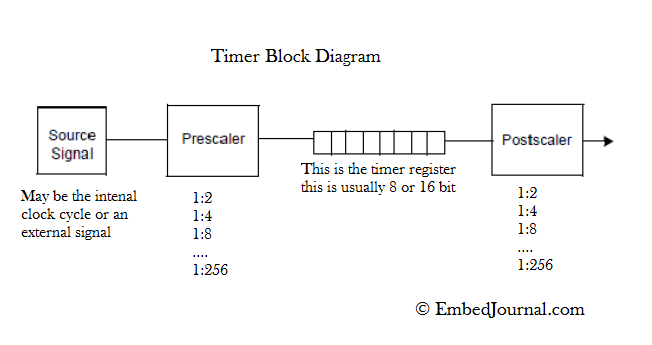
The prescaler and postscaler are specified in fixed ratios such as, 1:2, 1:4, 1:8 and so on. Depending on the size of the registers that hold the value they may range up to 1:256 or more. The concept of the prescaler and postscaler is the same. They are used to multiply a scalar value to the timer register value. But how and where they are multiplied is what makes the difference.
Understanding the concept of prescaler and postscaler:
The prescaler and postscaler are fairly common in most of the mid-range and advanced microcontrollers. They are provided as added feature and may or may not be used by the programmer. In a way they are one and the same. They both are used to control the overflow rate of the module.
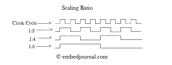
The value in the prescaler register defines the number of times the clock has to tick before the timer register experiences a single pulse. This can be visualized from the above image. The scaling ratio 1:2 means that the clock has to have a LOW to HIGH transition twice so that the output of the prescaler completes one HIGH pulse. This is one way of reducing the clock frequency. Hence by using this method, the timer register is essentially multiplied by ‘N’, where N is the value of the prescaler.
The postscaler concept is much similar to the prescaler. Only here, the value of the prescaler determines the number of times the timer register has to overflow to produce an interrupt. Therefore by using the postscaler the timer register value is multiplied by ‘M’, where M is the value of the postscaler.
Hence the net count C, after which the timer will cause an interrupt when both prescaler and postscaler is used is given by,
In case of an UP-Counter,
C = N x [timer-register-value] x M
In case of A DOWN-counter,
C = N x [(timer-register-value)-(maximum-value-timer-register)] x M
Having said this, you are now able to calculate the number of times the timer will count before it will interrupt the CPU. With this data at your disposal and the system clock frequency you can program the timer module to produce accurate time intervals.
Calculating the time interval for a given C value:
Frequency is basically, number of times something happens in one second. Tell that to any one and be sure you said it right, So a 20MHz of clock frequency is actually, 20 x 106 clock cycles in one second. To obtain the time taken for one clock cycle you will have to take the inverse of the frequency. In this case it is 1/20MHz which will give me, 0.05x10⁻⁶ seconds.
But not all the controllers take the machine clock as it is, it is scaled down by a factor, which varies from one controller to another, so this part is not controller independent as it was meant to be, You will have to refer to your datasheet to find out your scaling factor.
For now we will consider the PIC microcontrollers. Here the Fosc is divided by a factor of 4. So we have,
Fosc = 20Mhz
Fosc/4 = 5MHz
T = 1/(Fosc/4)
T = 1/5Mhz
T = 0.2 microseconds
So, one count of the timer will take 0.2 microseconds. Simple math tells us that C number of counts will take C times 0.2 microseconds.
Calculating the C** value** for a given timer interval:
This is just the reverse process of what we just saw, now we want to produce a time interval of say, 1 second. Here we have to the value of T and don’t have the value of C.
Timer taken for one instruction T = 0.2 microseconds.
Required time, Treq = 1 second
The the count value is obtained by, C = Treq/T
So, C = 1/(0.2x10-6)
C = 5x10⁶
It’s as simple as that. Now all you have to do is properly divide the count value into the prescaler, postscaler, and timer register. Once all the registers are set and the suitable interrupt settings are made, the controller will interrupt the CPU once every second and jump into the Interrupt Service Routine (ISR).
There are some cases when the C value is too big to be accommodated within the available register space (prescaler, postscaler, and timer register). This means that the time interval required is too big for the timer to produce. In this case you have resort to some other methods such as having a counter in the ISR so that the timer interrupt happens a certain number of times before the actual ISR is executed. But most of the applications require time intervals well below the maximum possible so you are not totally lost.
I hope this was helpful in understanding timer / counter modules and their interface. If you have any doubts or queries regarding this post please let me know and I will try to answer them to the best of my abilities.


