Over the past few days, I received a plethora of emails and messages on how to make a line follower robot. Mostly, the specification being white line on a black surface. Some even mentioned shortest path detection loops in the track. Now, I do get emails in which people ask me questions about line follower robots. Nope, thats not unusual (actually I get quite a lot).
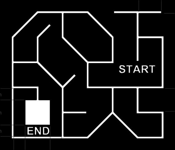
The unusual thing was majority of them seemed to give out similar track and robot description. Then I asked one of them to send me an image of the track, thats when I got to know about Mesh Flare, an Event in the TechFest-2016 a technical symposium organized by IIT Bombay. (Here is the full problem statement just incase they pull it down)
After looking at it for sometime, I had to get up and search for my college ID card (so that I too can take part in it), hoping that my year of graduation wouldn’t have been printed on the front.To my dismay, they did have it (very well pronounced).
Well that meant, I can’t actually take part in the event. Nevertheless I had spent some time thinking about it the previous day ,so I thought I will just make a small post on my ideas on the problem statement and how I would have approached it.
Of course I won’t spoil the fun for you. There will be no code at the bottom of this write up. So if you are looking for one, no luck here.
Here is the problem statement,
As always, you start at START and move through this maze and try to find your way to the big white square with the END below it. Now if you look at the track for a few seconds, you will observe that it has more than one loop in the track. This means, if you opt to use the all famous default-left or default right strategy, your robot is probably going to go in circles till it dies or the event coordinators kick you out. Honestly, the latter sounds more probable.
Now that can’t use conventional methods, how do we tackle this seemingly impossible problem statement?
Well it’s not going to be easy. But I can try to make it seem possible to a certain extent.
Your robot must,
- be able to follow a line (duh!)
- be able to detect 189, 90 and 45 deg direction changes. (not so tricky)
- be able keep a track of how far in space it has moved between any two points. (tricky)
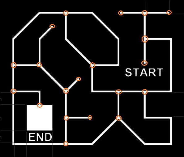
Now let’s take a closer look at the sample track that they have provided. There are certain points in the track where the robot has to make a decision. We will call these nodes ‘vertices’. Lets mark out all the vertices in the track.
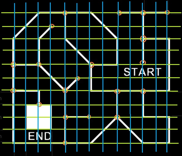
Yes, dead ends are decision making points. START and END are also decision making points. Now, some of you may have already observed that there is some niceness in the way the nodes are arranged. This is not just coincidence. Therein lies your secret. Now we will try to overlay a grid on the above image and see if we can make any sense out of it.
So, you can see that all the vertices can be made to fall on a grid and all motions happen from one of the 4 corners of each check on the grid. This check that we have defined here is going to be a single ‘unit-length’ on the arena. It’s up to you to define the resolution of this grid. Keep in mind that too much resolution is almost as bad as too little.
Now let’s think about what we have done so far. We managed to discretize the track into ‘unit-length’ checks and represent each check with an offset in space with (0,0) being the start vertex and (x,y) being the end vertex. This is a classic weighted directed graph.
Now you just have to perform a Depth First Search (DFS) on the graph to arrive at the destination node. If you have made it to this point successfully, choosing the least weighted path to the destination vertex should be a cake walk.
All the best for anyone participating. Let me know if this was helpful.


