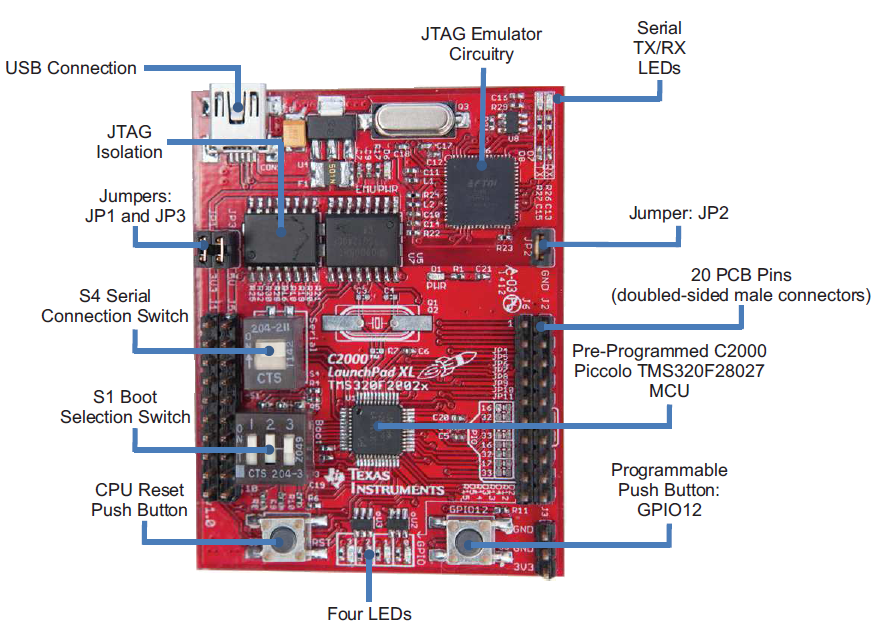
There is CCS (Code Composer Studio) IDE for programming and debugging the Launchpad. It includes an optimizing C/C++ compiler, source code editor, project build environment, debugger, profiler, and many other features. Also, the presence of Control Suite, a support software containing libraries and examples makes the learning easy.
Note: I will be referring to the C2000 by its family name as Piccolo DSC in this article.
LCD Interfacing part
For this post, I will assume that you are fairly acquitted with the basics involved in the interface of the LCD. We have covered that topic in detail at Embed Journal.For those who need to know the basics on interfacing LCD with microcontrollers read the post Interfacing LCD module with microcontroller by Siddharth. And as always, there are two modes of operation of the LCD 8 bit and 4 bit depending on the number of data lines you are willing to give for the interface. As I did not have any limitation on the number of pins available on the controller, I choose to use the 8 bit mode.
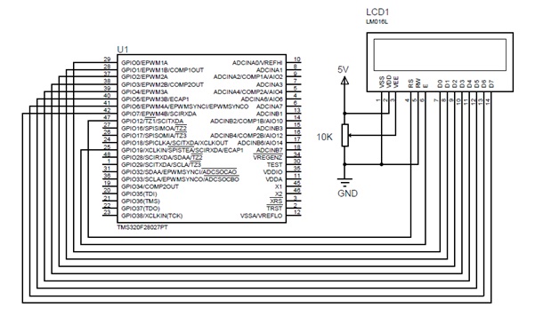
Circuit Diagram:
Piccolo DSC provides multiplexed I/O lines, so we need to carefully choose the I/O lines for interfacing the modules. The following image shows the pin mapping of 16x2 LCD with the Piccolo DSC. The R/W line is always tied to ground, since we are always writing to the LCD.
Initializing LCD
This function initializes the LCD interface. Initially, the Enable pin is held high and then four delays of 1600 microseconds are given. After that, hex value 0X38 is sent as the command for selecting the 8 bit interface.
Here, two delays were used. One is small delay of 50 microseconds and another one is long delay of 1600 microseconds.
After selecting the 8 bit mode, the commands for clearing the display, setting entry mode (cursor moving direction), blinking cursor and placing the cursor at home are given.
/* Initializes LCD */
void InitializeLCD(void)
{
    GPIO_setHigh(myGpio, E);
    LCDDelay1600();
    LCDDelay1600();
    LCDDelay1600();
    LCDDelay1600();

    WriteCommandLCD(0x38);            //Command to select 8 bit interface
    LCDDelay1600();

    WriteCommandLCD(0x38);            //Command to select 8 bit interface
    LCDDelay();                        //Small delay

    WriteCommandLCD(0x38);            //Command to select 8 bit interface
    LCDDelay();

    WriteCommandLCD(0x08);            //Command to off cursor,display off
    WriteCommandLCD(0x01);            //Command to Clear LCD
    LCDDelay1600();
    WriteCommandLCD(0x06);            //Command for setting entry mode

    WriteCommandLCD(0x0f);            //Command to on cursor,blink cursor
    WriteCommandLCD(0x02);            //Command return the cursor to home
    LCDDelay1600();
}
Writing Command to LCD
This function sends command to the LCD. First, the Register Select pin is set low before writing command. After that the command is written with the help of SendByte function. At the end of the function a small delay is given.
/* Writes a command byte to LCD */
void WriteCommandLCD(unsigned char CommandByte)
{
	GPIO_setLow(myGpio, RS);	    //Clear RS pin to write command
	SendByte(CommandByte);
	LCDDelay();				        //Small delay
}
Sending Byte to LCD
Here, the data pin is set to high or low according to the command or data received. This routine is used to write both data and command to the LCD. Each value is ANDed with the corresponding bit. If the result is 1, then the pin will be set high. If it is 0, then the pin will be set low.
At the end, the enable pin is set high and low as negative edge triggering is required for transferring the data from the register to the LCD. For this, a short delay has been generated using the for loop.
/* Send a byte of data to LCD */
void SendByte(unsigned char Value)
{
    unsigned char temp;


    if((Value & 0x01) == 0x01)
        GPIO_setHigh(myGpio, D0);
    else
        GPIO_setLow(myGpio, D0);

    if((Value & 0x02) == 0x02)
        GPIO_setHigh(myGpio, D1);
    else
        GPIO_setLow(myGpio, D1);

    if((Value & 0x04) == 0x04)
        GPIO_setHigh(myGpio, D2);
    else
        GPIO_setLow(myGpio, D2);

    if((Value & 0x08) == 0x08)
        GPIO_setHigh(myGpio, D3);
    else
        GPIO_setLow(myGpio, D3);

    if((Value & 0x10) == 0x10)
        GPIO_setHigh(myGpio, D4);
    else
        GPIO_setLow(myGpio, D4);

    if((Value & 0x20) == 0x20)
        GPIO_setHigh(myGpio, D5);
    else
        GPIO_setLow(myGpio, D5);

    if((Value & 0x40) == 0x40)
        GPIO_setHigh(myGpio, D6);
    else
        GPIO_setLow(myGpio, D6);

    if((Value & 0x80) == 0x80)
        GPIO_setHigh(myGpio, D7);
    else
        GPIO_setLow(myGpio, D7);

    GPIO_setHigh(myGpio, E);            //Set E pin to select LCD
    for(temp=0;temp<5; temp++);
    GPIO_setLow(myGpio, E);                //Clear E pin to deselect LCD
    LCDDelay();                            //Small delay
}
Displaying character in LCD
This function receives the line number along with the message to be shown in the LCD. Here, the message is received in the form of pointer array. For loop is used to send each character to the LCD. Maximum of 16 characters can be displayed in a row. Line number 1 and 2 are used to select the rows 1 and 2.
/* Displays a message on LCD */
void DisplayLCD(char LineNumber,char *Message)
{
	int	a;
	if(LineNumber ==1)
	{	//First Line
		WriteCommandLCD(0x80);		//Select the first line
	}
	else
	{	//Second line
		WriteCommandLCD(0xc0);		//Select the second line
	}
	for(a=0;a<16;a++)
	{
		WriteDataLCD(*Message);		//Display a character
		Message++;                  //Increment pointer
	}
	return;
}
Only necessary functions has been explained. For more information refer the code at the end of this article.
Using the functions
With the help of the above header file and source code, we can start using the functions in our own code. Here, I have written code for displaying the text in both the rows of the LCD.
Necessary header files have been included at the starting of the code along with our Piccolo_lcd header file. InitialGpio() function is used to initialise the I/O pins used for interfacing the LCD to output. For this the inbuilt setMode and setDirection functions are used.
In the main() function, the Watch Dog timer is disabled first in order to avoid unnecessary reset during the program execution. Then, the GPIO pins are initialised. After that, the LCD initialize function is called to initialize LCD. Then, the text has been displayed using the DisplayLCD function.
Hope this post will be of help in interfacing a 16x2 Character LCD with Piccolo DSC. The code used here can also be ported for any microcontroller families with minimal changes.


