Have you ever looked into the Arduino source files? Well you should be!!
I have been hanging around there for quite some time now. The Arduino Servo class has half a dozen functions to handle all the servo related tasks like the attach(), read(), write() and detach(). There was too much of AVR specific stuffs in there so I did not go very deep in to the code but looking at it helped me derive my own theories on how I have to structure the code. And as always, I am going to share it with you in this post!
It has always been like Arduino says, Let there be light and we always had a working servo motor. Now it’s time for us to write our own code instead of using some libraries!
What is a servo motor?
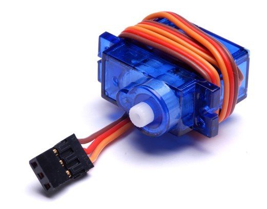
Servo motors are nothing fancy, they are just normal DC motors with an extra feature for error correction. In other words, DC motors fitted with a servo mechanism are called as servo motors. They have a potentiometer that is coupled to the shaft of the DC motor. So when the DC motor moves, so will the potentiometer that is attached to it.
The controller inside the servo motor reads the variation in voltage from potentiometer to get the position of the shaft from a look up table. This feedback mechanism is used to move the shaft to a desired position.
What they expect from us?
To begin with, servo motors expect one pulse for every 20ms (which is 50 times a second and a long way of saying 50Hz). So the servo motor’s signal wire will look for such a pulse, and measure the width of this pulse to derive the position. Based on this width (position data), the horn is then moved to the desired angle by the controller inside the servo motor.
Now that we know the width of the pulse is what that matters, we have to get into it. Please note that this data is just an approximation to help you understand the logic. The minimum and maximum timings for the pulse varies from one servo to another and it’s all dependent on the manufactures. Like always, read the datasheet that came with your motor.
| Pulse Width | Servo Horn Position |
|---|---|
| At 1ms | 0 degree |
| From 1ms to 1.5ms | 0 degree to 90 degrees |
| At 1.5ms | 90 degrees |
| From 1.5ms to 2ms | 90 degrees to 180 degrees |
| At 2ms | 180 degrees |
Sometimes the pulse range can be from 0.5ms to 2.5ms. This is the reason why Arduino has a feature to set the minimum and maximum pulse duration.
Is the servo motor signal PWM or PPM?
Then there is this question that has to be answered. This signal, though is modulated in width, is debated as to whether it’s PWM or PPM. There are a lot of forum threads where people have been discussing/debating this issue at length but I lost interest in reading them fully.
The answer is pretty straight forward it is PWM with a good tolerating capacity for the frequency. Yes it is PWM as there is no doubt that the width is varied and yes it looks like PPM and it is purely because the motor is very good at tolerating variation in frequency.
For example let’s say you are giving the motor 1ms ON pulse and 19ms OFF pulse and assume it points to some ‘X’ degree. Now if you modify your program to give 1ms ON pulse and 20ms OFF pulse, it’s going to point to the same ‘X’ degree [period].
By increasing the OFF time by 1ms, you would have changed the frequency and made it look like PPM but at the end of the day all that matters for the motor is the width of the ON pulse. It is rude to say that the motor does not care about the OFF time, it’s just that the motor is capable of tolerating some amount error in it.
Programming logic!
As promised earlier we will get to the programming logic without any more chit chat. Now you might ask why we need any programming logic if the signal is PWM, yeah I know your controller has a PWM module in hardware but if I am not very much mistaken I don’t think you can bring it to work at 50Hz and even if you did, it will be a terrible waste of resource to control one servo with a native PWM channel.
It’s kind of hard to explain the concept in writing so I made a video explaining the logic.
I hope that the video explained the programming concept very clearly. If you have any questions regarding the details presented in the video please leave a comment and I will get back to you ASAP.
Now assuming that you have made a program that will interrupt every 0.1ms, all you have to do is to have an up counter variable that counts from 1 to 200 (which is from 0.1ms to 20ms). Then have another variable inside the ISR which will hold the data for the pulse width.
For example, let’s say you want the width to be 1.8ms. All you have to do is multiply it by 10, which gives us 18 and subtract it from the max value of the counter (which is, 200-18 = 182) and store it in the width variable.
Every time, the counter variable value becomes equal to the width variable’s value, set a GPIO pin (ON). And whenever the counter variable reaches the max value (200) clear that GPIO pin (OFF). You would have effectively produced a signal that the servo motor can understand!
Assuming you have configured the timer interrupt to fire at 0.1ms and you have defined the variable count and widthCount, here is how you ISR should look like.
void interrupt timerISR(void)
{
    if(timer_interrupt_flag) {
        count++;
        if (count > 200) {
            count = 0;
            serovoPin = 0;
        }
        if (count == widthCount)
            servoPin = 1;
    }
}
I hope the write up was to the point without any confusions. If you have any questions/suggestions, please leave a comment here and I will respond at best. In my future posts I will demonstrate the working of a servo motor with the logic explained above.


