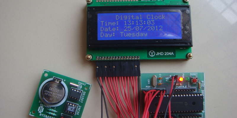
Digital clocks are are very commonly (cheaply) available these days. Some of them have a built in RTC to keep the time running even if the main battery fails and some of them don’t. In either case, for a standalone embedded application to get time, an RTC in almost the only reliable solution solution available. Most of these clocks use a 7-Segment display to display the time and date while some use LCD displays. In this post we will see how to make a digital clock with DS1307 and PIC 18F4520.
Besides this is a project to show off your geekish skills to the world. Make a digital clock all by yourself and hang it in your room and let the presence of an engineer be known!
What does it take to make a digital clock?
Other than time and effort you will need the following components to make a digital clock.
- PIC Microcontroller - PIC18F4520.
- LCD Display
- RTC DS1307
- CMOS Battery and its slot.
Prerequisite
For this tutorial I assume you have a working knowledge about the I2C Protocol, and you know hot to interfacing DS1307 an get date and time out of it. We will also interface character LCD to display the date and time.
If you do not know any of the above please read through them first and then get back to this post you can follow the links to read all the relevant posts (if it’s not very obvious).
You can find the sources for this project at our github page.
Now that you know how to read and write data to the RTC, all that is remaining is to get the values form an RTC’s timekeeping registers and display them in the LCD display. This is how we are going to arrange the received data on the screen,
I use a 20x4 line LCD display. Here is the Display Data RAM addresses to which the data will be written to. The source code below will use this table as the reference for the display. If you are using an LCD with a different configuration, you might have to modify the DD RAM address accordingly for this code to work. Look into your LCD’s datasheet.
For making this digital clock, you will have to acquire information on the time, date and day form the RTC. After getting them you will have to display them on the LCD display. The time and date information that is read form the RTC is not in a format that can be displayed on the LCD. So we have to do some processing before the data can be printed to the LCD. For this we will write some subroutines that will take care of the job.
Here is a function that basically calls the other subroutines that actually does all the processing of the data. So this is just a wrapper function so that we don’t have to call the individual functions separately.
void display(void)
{
    time(get_time(2),get_time(1),get_time(0));
    date(get_time(4),get_time(5),get_time(6));
    day(get_time(3));
}
We will also need two global variables ‘units’ and ‘tens’ for splitting the data into higher nibble and lower nibble (in case of the RTC its the tens digit and units digit of the data)
Display the Time
This function is used to display the time in the LCD display. It takes the time value as a parameter and converts them into printable data and puts them in their corresponding positions in the display. Again this is a code for the 20x4 LCD. If you have some other module modify the DD RAM address.
Note: the variable units and tens are global variable and are updated every time the decode() is called.
void time(unsigned int hours,unsigned int minutes,unsigned int seconds)
{
    decode(hours); // separates the variable into higher and lower nibble
    if(tens>3)     // To set AM or PM
    {
        if((tens == 6)|(tens == 7))
        {
            LCD_cmd(0xCF);
            LCD_data('P');
            LCD_data('M');
            tens=tens&1;
        }
        else if((tens == 4)|(tens == 5))
        {
            LCD_cmd(0xCF);
            LCD_data('A');
            LCD_data('M');
            tens=tens&1;
        }
    }
    else
    {
        LCD_cmd(0xCF);
        LCD_data(' ');
        LCD_data(' ');
    }
    LCD_cmd(0xC6);
    LCD_data(tens+48);   // Add 48 to display ASCII value of number
    LCD_data(units+48);

    LCD_cmd(0xC9);
    decode(minutes);
    LCD_data(tens+48);
    LCD_data(units+48);

    LCD_cmd(0xCC);
    decode(seconds);
    LCD_data(tens+48);
    LCD_data(units+48);

}
Function to display the Date, Month and Year
The date, month and year values read from the RTC are provided as parameters for this function. Here the numerical (decimal) data is translated to ASCII values and are written to the LCD module at appropriate character positions.
Note: the variable units and tens are global variable and are updated every time the decode() is called.
void date(unsigned int date, unsigned int month,unsigned int year)
{
    LCD_cmd(0x9A);
    decode(date);
    LCD_data(tens+48);
    LCD_data(units+48);

    LCD_cmd(0x9D);
    decode(month);
    LCD_data(tens+48);
    LCD_data(units+48);

    LCD_cmd(0xA2);
    decode(year);
    LCD_data(tens+48);
    LCD_data(units+48);
}
Function to display the Day
The day is represented as a number (with 0 representing Sunday) in the RTC time keeping registers. A switch case was the most common way to decode it into the actual day and print it on the LCD display
void day(unsigned int disp){
    LCD_cmd(0xD9);
    LCD_data("                ");   // to clear past memory
    LCD_cmd(0xDA);
    switch(disp){
	case 1:LCD_string("Sunday");
               break;
	case 2:LCD_string("Monday");
               break;
	case 3:LCD_string("Tuesday");
               break;
	case 4:LCD_string("Wednesday");
               break;
	case 5:LCD_string("Thursday");
               break;
	case 6:LCD_string("Friday");
               break;
	case 7:LCD_string("Saturday");
               break;
    }
}
Besides these functions, we will need a function to decode the data into the units and tens place. This function also updates the values of the global variables units and tens.
// Function separates the variable into higher and lower nibble
void decode(unsigned int val)
{
    tens=val>>4;
    units=val&0x0F;
    return;
}
Now all that you have to do is to collect all these functions and put them in a file called clock.c and create a clock.h to be included in your main program.


