After publishing the article Make a simple RC car I have received a lot of comments and e-mails from readers who have faced some difficulties while trying to make the circuit by themselves. I have complied a small list of testing methods for various components that will help your narrow down the causes of malfunction.
Like always, we will have to split the entire circuit into various segments in order to test them. So there are four major places where problems may arise.
- In the power circuit
- In the motor driver circuit
- In the encoder or decoder ICs
- In the RF transmitter and receiver modules
Power Circuit
The problems in the power circuit are fairly easy to detect so I wont get into the details. Most of the time it is short circuit due to an improper soldering or due to a bricked component. In either case the battery would heat up and the power LED would not glow.
Solution: All you have to do is power off the circuit and then test for short circuits with a multimeter in connectivity mode. If there is a short, then look for the source of the short and try to eliminate it.
Motor Driver Circuit
The L293d ICs are fairly easy to brick. Most of the time you will see a visible damage on top of the IC (there will be crack). If you are lucky you will be able to see the smoke too, but there are some cases when the IC is bricked without any external signs.
Solution: Give +5v and GND to the IC’s power terminals and then give the high voltage supply VCC2 to pin number 8. Also connect the enable pins of either motors to +5v so that they are always enabled. Now give Logic 1 and Logic 0 to the input of one motors and check the output pins with a multimeter. You should get VCC2 in the multimeter if you don’t get it then you have to replace the IC
Encoder and Decoder IC
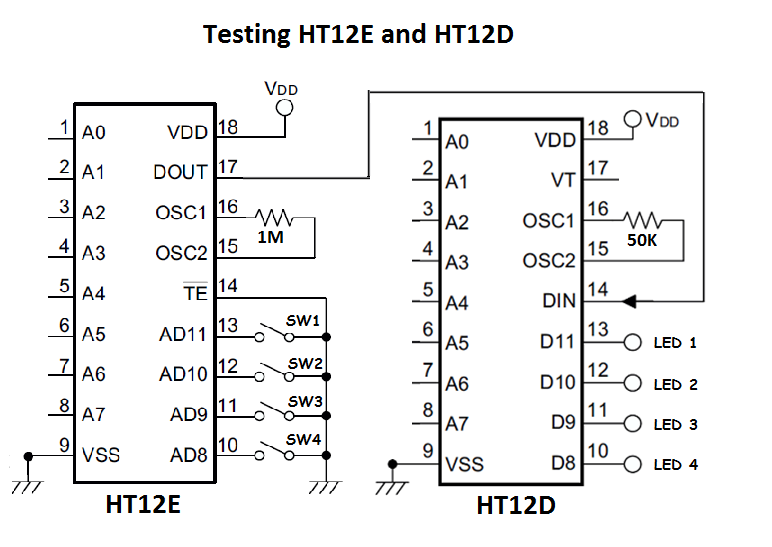
This is a very uncommon fault but it has to be ruled out any way to be certain that your encoder and decoder pair are working properly. You will have to short the DOUT pin of the Encoder to the DIN pin of th Decoder. You have effectively removed the RF module alone from the circuit. This will remove any trouble caused by the RF module. Here is small video that I have made to demonstrate this concept.
Solution: Unfortunately there is not much you could do about it. So buy another one.
RF Transmitter and Receiver Module
If you have followed all the above steps and reached here without falling into any of the categories, then you can be almost be sure that the problem is with your RF transmitter or receiver module.
Solution: Unfortunately there is not much you could do about it. So buy another one.
Besides that there are other places where things can go wrong. Your best bet is to trust your gut and work on instincts to solve the problem. You may want to read other tips and tricks on circuit debugging to be better equipped to tackle the situation.


