Most of the time your breadboard will just need a 5 volt supply to power all the components. Very rarely you might need a 12 volt (if you are driving loads like motors) or 3.3 volt (devices rated at 3v3). In this post we will see the making of a breadboard power supply, mostly from components that you will find off the shelf.
Now there are various methods for doing this.
- Build a 5 volt regulator on the breadboard and give it a standard 12 volt supply.
- Use an RPS to set a 5 volt output.
- Use an external regulator board probably with 7805 to provide a 5 volt output.
All the above methods though solves the purpose, is not the best way to do it. Here is why you cannot use those methods in the same order as they appear.
- A lot of space is occupied by the 7805 and its related circuity. There is practically no straight forward method to mount a 3 mm DC Jack connector on the breadboard.
- RSP! the name sounds BIG. The mobility of the setup is lost.
- Though this is the best among the available options, this isn’t the best way to do it either.
To what end?
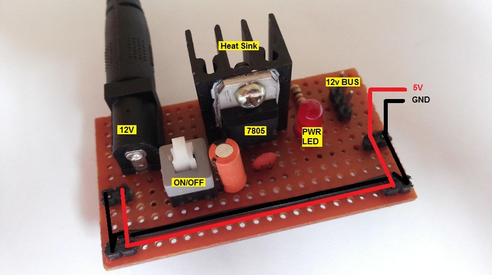
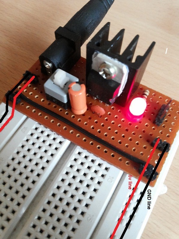
By the end of this short post you should have, (if you are going to be doing it as you read) or have the knowledge to make, something like this.
Its pretty clear from the image that we have a 3 mm DC Jack connector to plugin out 12 volt (or 9 volt) supply, an ON/OFF switch, a couple of capacitors, the 7805 with a huge heat sink attached to it, a power LED and a strip of male header pin for 12 volt supply.
Watch out
Now if you noticed clearly, I have made a mistake here. I have soldered the male header pins to the 12 volt bus. Given that I’m building this circuit for the breadboard, I should have used a female header strip. If I had done that it would have been 100% breadboard compatible. But now, I have to connect a female to male jumper to use the 12 volt supply. So watch out while making one of these.
So let’s begin!
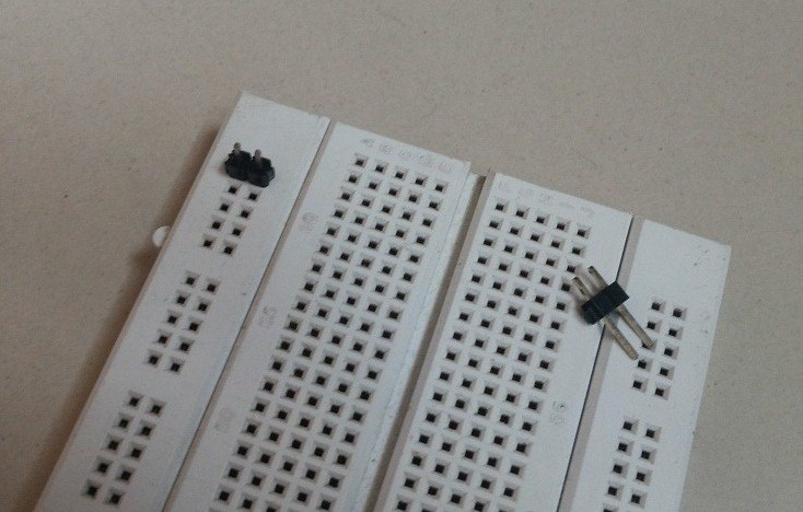
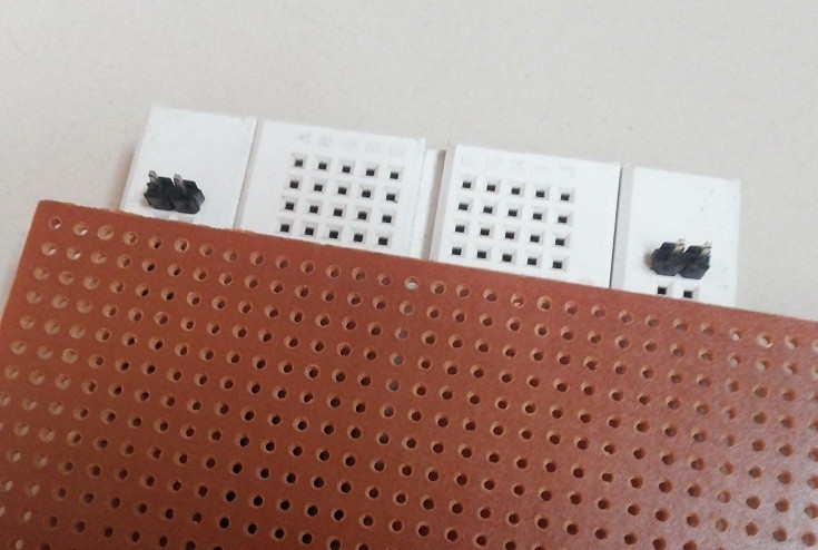
First you will have to cut out a pair of 2 pin male header from the strip. Then plug them into the power rails of the breadboard as shown in the second image. Now take a GP board and compare the holes they have on them with that of the power rails of the breadboard. Your task is to find a hole in the GP board that will match with the ones on the breadboard.
For doing this you can place the GB board over the header pin and see if the top portion of the metal will fit into any of the holes without any force. The prototyping board (GP board) is a standard 0.1 inch spaced board. So you should be able to find out a hole that matches our description without much trouble.
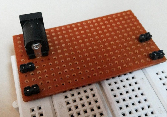
Once you have found a suitable hole, use a marker pen to make a note of it. Now from experience, I found that adding another set of header pins as shown in the fourth image, considerably increases the mechanical stability of the circuit. So you can choose to either add this redundant pin or forget it. But trust me you will love it.
After this, its just the circuitry. You will have to built a 5 v regulator circuit. Once you have all the components soldered on to the GP board you should have something like this. But don’t power it up.. not yet.
That’s right you will have to test it before putting it to use on the breadboard. You most likely made some mistakes in the soldering or there is a short circuit. Now a short circuit in the power lines could mean total chaos. So use the continuity(connectivity) feature of your multimeter to check if there is any short circuits. Once you are 100% sure that there is no problem with your connections, power the board and see if the LED goes ON. If it does not turn ON or if it is glowing dim, then there is some short circuit that was overlooked while testing. Power OFF the board immediately and start testing again.
Conclusion
Should every thing go well, you will have a good low cost breadboard power supply which does exactly this,
Hopefully this image will help you remember which line is GND and which line is 5 volt. I choose this combination because it will be easy to remember that the outer most power line is always GND and the inner one is 5v. You are free to choose which line is for what.

