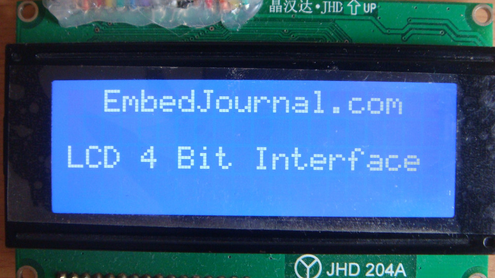
This post documents the steps involved in interfacing the LCD in 4 bit mode with a microcontroller. It belongs to a series of 4 posts. If you landed here straight from a search engine, here is an index to help you navigate.
- LCD Module Basic Theory (LCD Controllers, CG&DD RAM, PIN description,Timing Diagram, Commands)
- Programming LCDs in 8 bit mode (programming pic18f4520 in C with C18 compiler under 8 bit mode)
- Programming LCDs in 4 bit mode (programming pic18f4520 in C with C18 compiler under 4 bit mode)
- Creating Custom Characters (bit map symbols and arrows that are not usually present in the ASCII table)
Embedded applications are always developed on controllers whose resources are almost fully used in order to cut the cost of the product. This is done especially in applications that do not need any future expansions or a firmware updates. They are Make-it and Forget-it kind of applications. Most of the time, either the memory or the available pins are in demand. In some cases both memory and pin count are less.
The Character LCD in 8 bit mode uses 8 data lines and 3 control lines to display characters. This kind of interface is costly in terms of pin usage. Most of the industrial applications use the LCD in 4 bit mode. The total data lines needed is reduced by half in this mode. I have already discussed this in one of my previous posts on the Theory behind the LCD modules. It is further possible to reduce the Port Pins required by asserting the R/W pin permanently LOW throughout the interface. By doing this we mean that the LCD will always be operated in Write mode and Read mode will not be used. This way another pin can be saved.
The interface of LCD in 4 bit mode without checking for busy flag can be little tricky and we have to give enough delays calls between data latch and next data write to insure that the LCD is never busy while a new data is written to it. This post will deal the programming of LCD in 4 bit mode with the R/W line of the LCD pulled low. Hence this interface will just use 6 pins of the interface.
Basic understanding:
The 8 bit data is split up into two chucks of 4 bits each. The higher nibble is sent first and then the lower nibble is sent to make one complete data transfer. Since each byte is transferred in two steps the speed of this method will theoretically be doubled. Also, we are not using the busy flag to monitor the state of the LCD so this introduced a further reduction the speed of the execution. We can get the commands that will make the LCD understand that we will be sending data in nibble format from the LCD’s datasheet.
Connection:
The connection is really simple and it is quit self explanatory. Here are some images to help understand the wiring better. There are a total of six pins (4 for data and 2 for command) that are connected to the PIC 18F4520 Microcontroller sitting over the ZIF (Zero Insertion Force) socket.
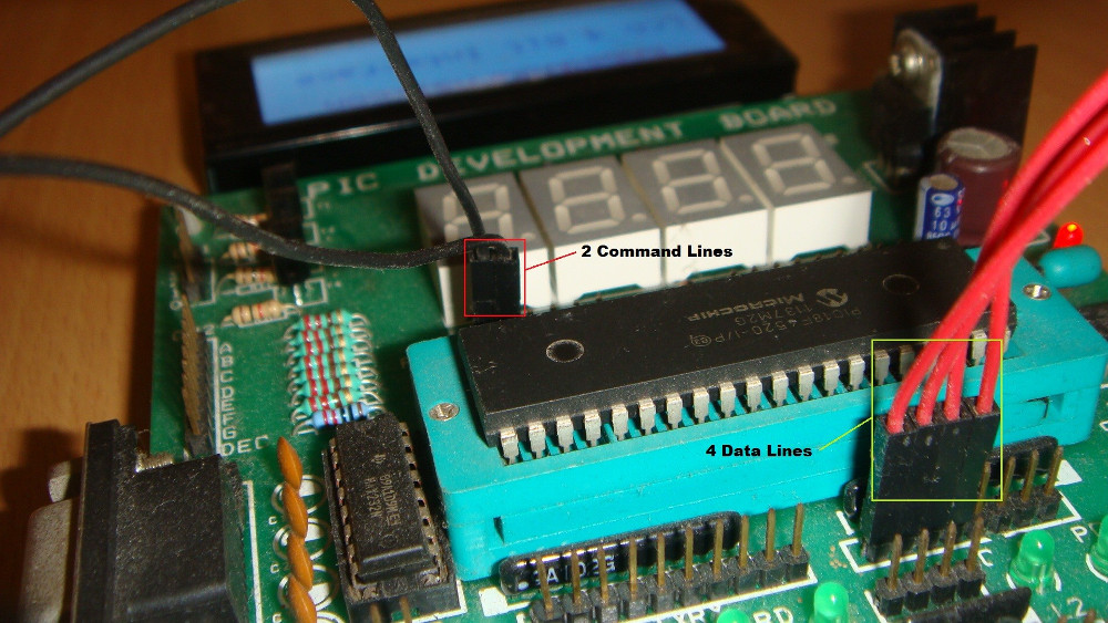
I’m using a development board that provides a breakout board for LCD displays. The Gnd, Vcc, Contrast, BL+, and BL- pins are internally connected to the power supply and potentiometer. So you will notice that I am not connecting anything to those pins.
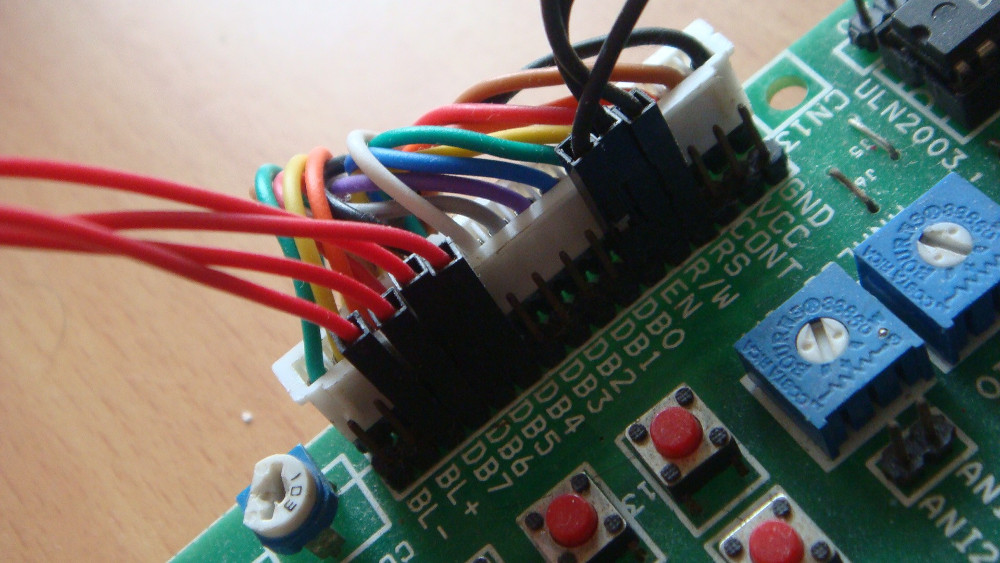
In the above image you can see 7 wires that are connected to the Male Header pins. The R/W pin has to be grounded externally as it is not internally grounded. The white connector behind it is the 16 wire RMC connector that I am using as an extension cable form the LCD module.
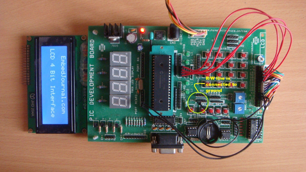
Here is the entire setup. It shows how the R/W pin is held low throughout the interface. While designing PCB’s we can connect this permanently to ground or provide a jumper just in case we need to check the busy flag.
Programming:
Here also we will be using the same functions. Only the lcd.c and lcd.h file have to be modified, the main.c has also been changed but the logic is the same. Also most of the function and how they behave has been discussed in my previous post, programming LCD in 8 bit mode. So I will not rehash them here and make this post lengthy.
/*
 * File Name: basic_4bit_interface
 * Author: Siddharth Chandrasekaran
 * Created On: 3rd July 2013
 * LCD Library For C18 compiler and PIC advanced 8 bit CPUs
 * Visit http://embedjournal.com for more codes.
*/
#include"p18f4520.h"
#include"delays.h"
#include"lcd.h"

void LCD_init(void){
    EN=LOW;
    RS=LOW;
    LCD_port=0x00;
    LCD_reset();
    LCD_cmd(CLRSCR);
    Delay10KTCYx(50);
    LCD_cmd(MODE_4BIT);
    Delay10KTCYx(50);
    LCD_cmd(DISPLAY_ON | CURSOR_OFF);
    Delay10KTCYx(50);
    LCD_cmd(CURSOR_INC);
    Delay10KTCYx(50);
    LCD_cmd(LCD_LINE1);
    Delay10KTCYx(50);

}

void LCD_reset(void)
{
    Delay10KTCYx(2);
    LCD_port=0x03;
    EN=HIGH;
    Delay10KTCYx(50);
    EN=LOW;

    Delay10KTCYx(1);
    LCD_port=0x03;
    EN=HIGH;
    Delay10KTCYx(50);
    EN=LOW;

    Delay1KTCYx(1);
    LCD_port=0x03;
    EN=HIGH;
    Delay10KTCYx(50);
    EN=LOW;

    Delay1KTCYx(1);
    LCD_port=0x02;
    EN=HIGH;
    Delay10KTCYx(50);
    EN=LOW;
    Delay1KTCYx(1);
}

void LCD_data(unsigned char data)
{
    unsigned char temp;
    temp=data;
    RS=HIGH;
    //sends the upper four bits
    temp=temp>>4;
    LCD_port=temp;
    EN=HIGH;
    Delay10KTCYx(50);
    EN=LOW;

    //sends the lower 4 bits
    temp=data;
    LCD_port=temp;
    EN=HIGH;
    Delay10KTCYx(50);
    EN=LOW;
}

void LCD_cmd(unsigned char cmd)
{
    unsigned char temp;
    TRISD = 0x00;
    RS = LOW;
    LCD_port_dir = 0x00;
    temp=cmd;

    //sends the upper four bits
    temp=temp>>4;
    LCD_port=temp;
    EN=HIGH;
    Delay10KTCYx(50);
    EN=LOW;

    //sends the lower 4 bits
    temp=cmd;
    LCD_port=temp;
    EN=HIGH;
    Delay10KTCYx(50);
    EN=LOW;
}

void LCD_string(const rom char *buffer)
{
    while(*buffer)              // Write data to LCD up to null
    {
        Delay10KTCYx(50);
        LCD_data(*buffer);      // Write character to LCD
        buffer++;               // Increment buffer
    }
}

void LCD_blink(void)
{
    LCD_cmd(DISPLAY_OFF);
    Delay10KTCYx(255);
    Delay10KTCYx(255);
    LCD_cmd(DISPLAY_ON);
    Delay10KTCYx(255);
    Delay10KTCYx(255);
    LCD_cmd(DISPLAY_OFF);
    Delay10KTCYx(255);
    Delay10KTCYx(255);
    LCD_cmd(DISPLAY_ON);
    Delay10KTCYx(255);
    Delay10KTCYx(255);
}
Note: The delay function call will vary from one oscillator frequency to another. This code was tested for 20MHz oscillator. Make necessary changes so as to suit your system clock frequency or else this code may not work.


