Whether you are an engineering student building a multi terrain vehicle or an electronics hobbyist trying to impress people with your skills, making a RC robot car (wireless) is much better than the wired robot which you will have to tail while driving.
This is not exactly a robotics project. By definition, a robot is something that makes a decision based on some external parameters. There is one hell lot to do before going around telling people ‘I build robots’ but hey, you got to start somewhere right?
Objectives
We will discuss a basic ‘Land Rover’ with nothing. Well not exactly nothing, but nothing complex. As I mentioned earlier this is a really simple project, so simple that not even have an embedded computer (microcontroller) in it.
The emphasis is just on the mechanical design and some basic circuitry. We learn the interface of the commercially available RF transmitter and receiver module coupled with HT12E and HT12Dpair (Encoder/Decoder) to transfer data over the air to the motors in the our robot car.
Things you will need:
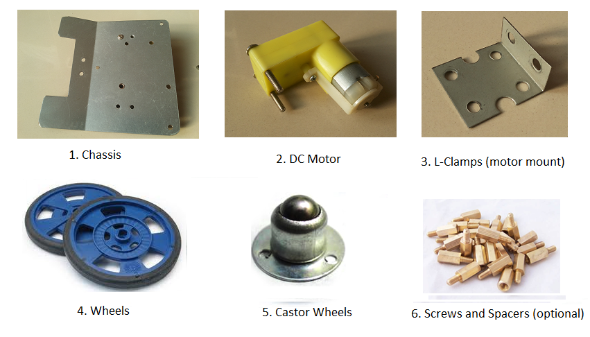
Most of the components that we will be using are really common and can be bought in local electronics stores. Here is a list of all the hardware items that you will need for this project.
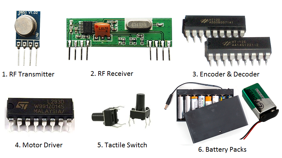
And in terms of electronics, you will need the following major components. You may also need some other basic components such as resistors and capacitors but we will discuss them as and when we get it.
Other than the above components, you will need a basic supply of tools, soldering iron, and related stuffs.
So lets get started!!
Working Logic for the RC Robot Car
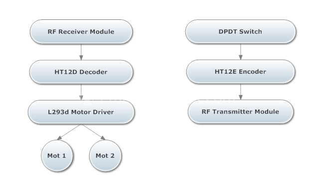
Here is a flowchart to help you understand the working logic of the robot car. First we will go over the basic idea of the RC car and the working logic that is involved in the car. There are two blocks, the Transmitter (remote control) and the Receiver (robot car).
On the transmitter side, you have the switches to give the digital inputs to the encoder IC. The encoder then encodes this data and sends it to the the RF Transmitter module.
On the receiver side, you will have the RF Receiver which receives the encoded data and passes it on to the decoder. The decoder decodes the data and sends it to the motor driver IC to drive the motors.
Understanding Datasheets
The next step is to learn how to access the data sheet for the components that you are using. Its actually not that big a deal, just Google the component name and you will find links to the datasheet.
The data sheet or spec sheet is a PDFA document that is provided by the manufacturer to give us a better understanding of how the component actually behaves. The real tricky part is to find what you are looking for in the PDF file that you just downloaded.
Reading and understanding the data sheet is a skill that any electronics enthusiast should master. I suggest you read the article Are you reading the datasheet? What to look for and how to find them! to learn how to read and understand datasheets.
So the point is spend enough time with the datasheet. You can be almost be 100% sure that every minute was well spent.
Differential Drive Algorithm
There are a lot of different types of drive algorithms for driving robotic cars. One such method is the differential drive method.
I know it sound fancy but that’s no big deal. We will be using only one pair of motors to drive the car. Check out he video for seeing how the hardware is connected. We will just have one castor wheel asides from the two motors and it will be used to give mechanical stability to the robot car.
Now the obvious question is how will the car change direction if it has only two wheels. That is when the differential drive algorithm comes in the picture. The direction control is achieved by rotating one of the wheels in one direction and the other in another direction. The following table might give you a better understanding.
| Left Motor | Right Motor | Direction |
|---|---|---|
| Front | Front | Front |
| Front | Back | Right |
| Back | Front | Left |
| Back | Back | Back |
As you should have guessed, the car will go front or back if both the pair of motors operate in one direction and left or right if they operate in different directions.
RF Transmitter and Receiver Module
Now here is what the RF transmitter and receiver modules will look like. There are a variety of manufacturers so don’t panic if your modules are looking different. Even the frequency in which they communicate should not be a problem as long as both the receiver and the transmitter are of the same frequency. All modules are Pin and Pad compatible. But there are some modules that have inverted numbering, like first pin will be last pin and second pin will be second from last and so on.
Making the RF Transmitter (Remote Control)
Now for the transmitter circuit, you will have to bear in mind that this is your remote. So try to make it as handy as possible (in case you are making one). Trust me, the last thing you want is a remote that is too big/heavy to carry around. Make a good closure for this circuit.
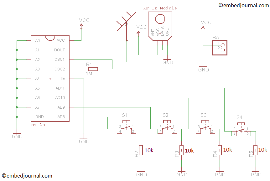
The HT12E encoder are 12 bit encoders that is they have 8 address bits and 4 data bits. The address bits can be left open or pulled low. In the circuit below, you will see that each of the address pins (A0 to A7) are connected to a switch. So if the switch is ON then that line is connected to GND (VSS) otherwise the pin is left floating.
The TE (transmit enable) is an active low input to the IC. This enables the transmission. So when the switch connected to pin 14 is pressed, the 8 address bits along with the 4 data bits (AD8 to AD11) are serially encoded and sent out at the DOUT pin.
For our application (RC robot car) we will connect TE directly to GND as we have to keep sending the data as and when they arrive to the rc car.
Unlike the receiver circuit, this does not need to have a beefy battery. You could power this circuit with a 9V battery.
Click on image to enlarge it!
Making the RF Receiver Circuit with Motor Driver
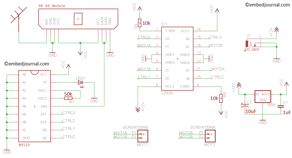
This is the circuit diagram for the receiver. It handles the RF reception as well as the the motor drive.
The address pin in the decoder (HT12D) behaves just like that of the the encoder. The data is received at the DIN pin from the RF receiver circuit and then this data is checked 3 times (according to the datasheet the data is transmitted 3 times and received 3 times and only if all 3 times the data is same it is decoded) and then decoded and the IC checks if the address pin connection of the encoder is same as that of the decoder. If the address configuration of the decoder matches that in in the received data (from encoder) the data is decoded and latched on to the data pins (D8 to D11).
This decoded data is then sent as control signals to the motor driver IC. L293d is a dual H-bridge motor driver to be short. It is used to drive the motor in both forward and back ward direction. Read about the basics of DC motor drive and their speed control to get a better understanding of this concept.
The VT (valid transmit) pin is used to indicate if there is a valid transmission between the encoder and decoder. This pin can be left open or like in the circuit below, an LED with series resistance can be used to give a visual indication.
Click on image to enlarge it!
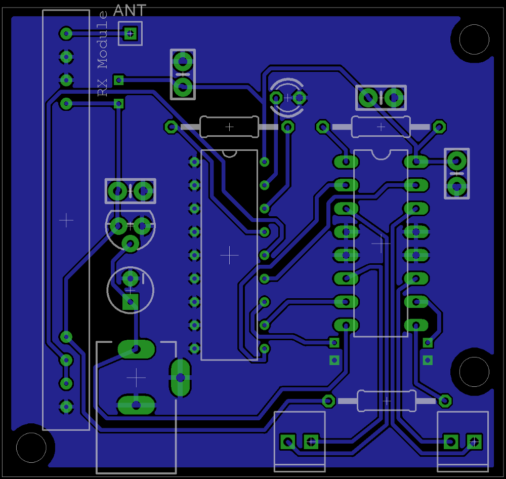
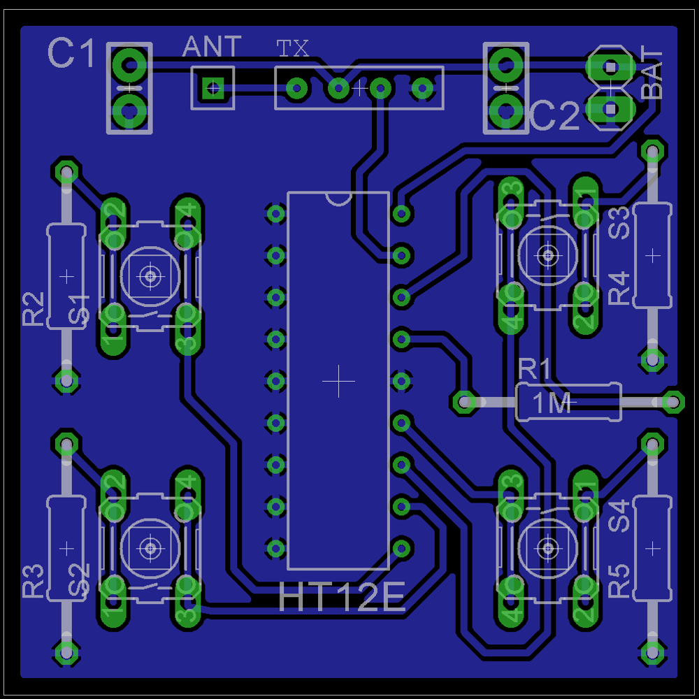
PCB Art work
I took some time to create a small PCB layout for the above two circuits. You can download the source file for the eagle designs and printable PCB artworks from here. I’ve never done any circuit design as a profession. This is a skill that I picked up somewhere on the run and its rather primitive. So this might not be the best layout possible but it did work for me. I’m willing to accept any help in improving this design (write to me) to help the others.
Update (April 2016): I will be unable to support this design as I have lost the original source files. Please use them only as a reference to your own design. And if you do make one good enough to share, contact me to put up your work here.
Video Demonstration
This is a video that I have made documenting the entire process of making the RC car. If you have read all the points that I have mentioned so far, nothing I talk about in this video will be new to you. I just made this video to give you a better understanding of the steps involved in making you on RC robot car.
And please excuse my poor video making/editing skills. I am yet to master them.
Testing your Circuit
Since this post was published, readers have have run into various kinds of problems while trying to make the remote controlled robot car. Most of the time the problem they encountered was in RF Transmission and Reception section. It also fell into specific categories when the problem was not in the RF section.
Please read the article on how to test your RF transmitter and Receiver circuit in case there is a fault.
I strongly suggest you to read the post Circuit Debugging - Tips Trick and Techniques before attempting to make your own RC robot car. If you are still having any doubts, post your comment in that article and I will try my best to help you out.
In the mean time you might want to read about some more advanced robots that we have in our Robotics Archives. For making any robot you should have a reasonably good knowledge on embedded systems and basic electronics and mechanics.
You might want to check out these posts for your future projects!!
- Hack a Toy Car to Make a Cheap Wireless Robot
- How-to: Make a Chassis For Your Robot
- Line Follower Robot
That’s all for getting started to robotics (well it is not exactly robotics) There is a lot more to learn beyond this point. This should have cleared some of the basics up for beginners and a refreshment for the advanced readers. Hope to see you soon with another such article.
